← All projectsScience OlympiadDec 2024 to Apr 2025
Science Olympiad Robot Tour
A navigation robot on an optical flow sensor, and a lesson in accumulated drift.
I built this robot by myself for the 2024-25 Science Olympiad Robot Tour event, where a robot finds its own way around a 2 by 2.5 m track, through gate zones and around wooden 2x4s, to a target point. Two Axon MINI servos drive it through a 2.5 : 1 spur gear stage, a SparkFun optical tracking odometry sensor (OTOS) underneath tells it where it is, and an Arduino Mega runs the route as a list of moves, each closed with distance and heading control that carries the last move's leftover error into the next.
The first version drove the wheels with belts, which had a lot of friction in the printed frame, so I rebuilt the drive with gears on the same centres. The weak link in the end was the OTOS: it drifted, and the robot's idea of where it was slowly pulled away from where it really was.
The robot in 3D
Both versions of my CAD, turned by the scroll.
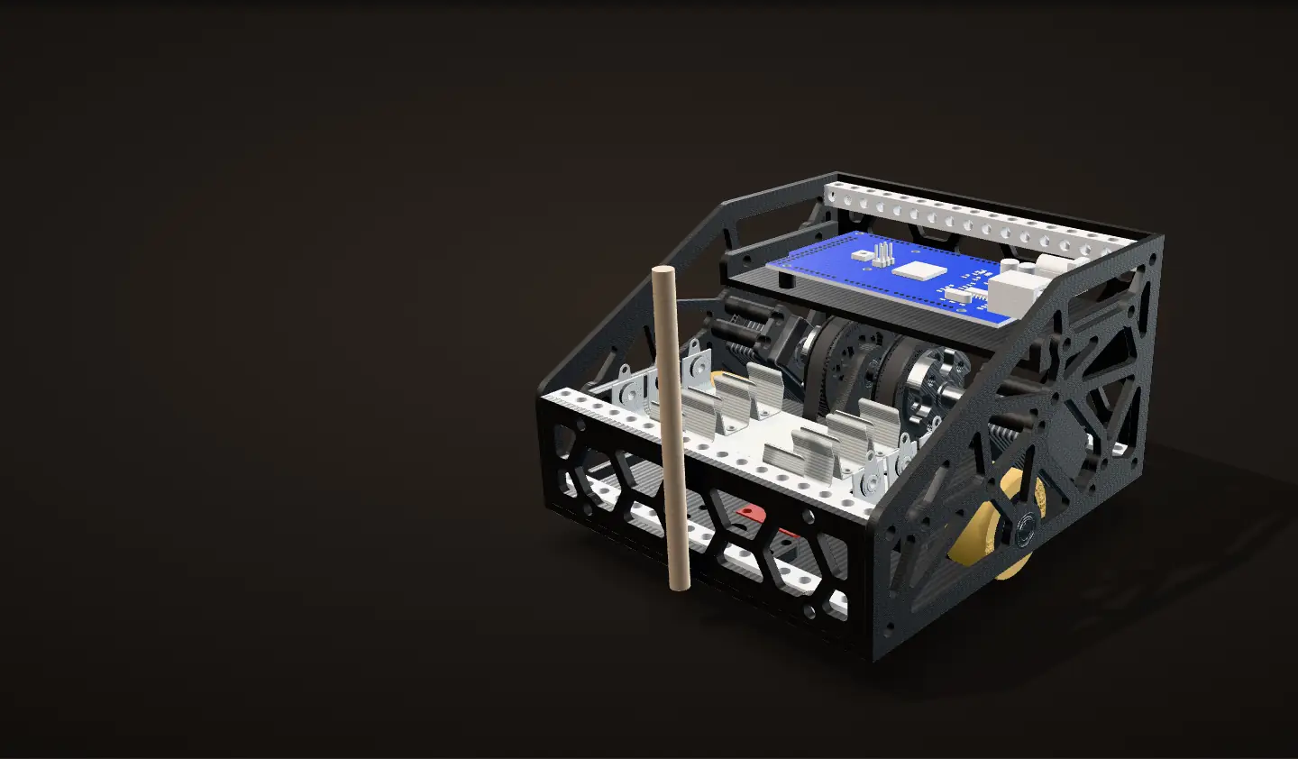
Version 1: belts, December 2024
About 14 by 16 cm on a 3D-printed frame (from the CAD): lattice side and end plates, a bottom plate, and a deck for the Arduino Mega, tied together by four goBILDA beams. Each wheel is driven through a GT2 belt from an Axon MINI servo.
Version 2: gears, March 2025
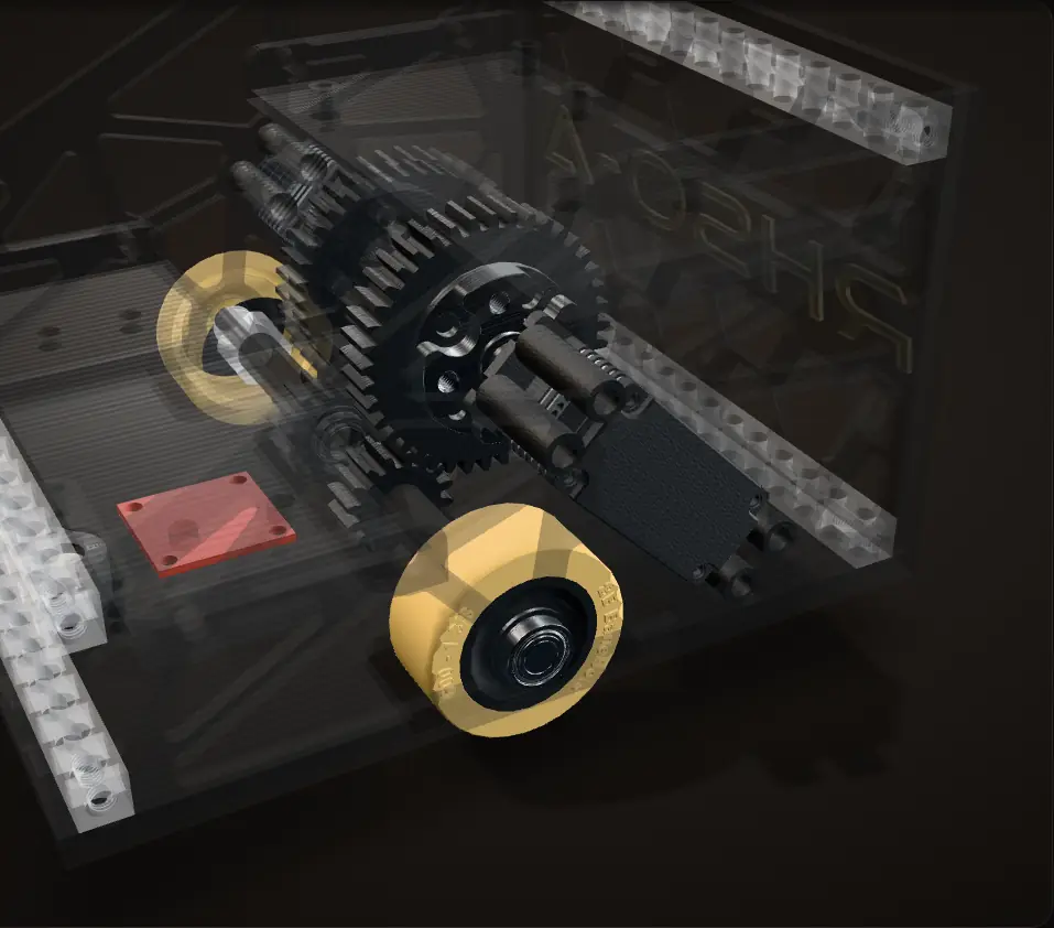
The same servos, axles and wheels, with spur gears in place of the belts, and a pointed nose on the bottom plate that holds the dowel, the point the judges measure from. In version 1 the dowel stands in front of the frame with no holder.
Taken apart
The two drive modules are mirror images: servo, gear pair, axle, two bearings and a wheel each. The OTOS sits under the middle, with a ball caster ahead of the wheels and one behind, all on the centre line.
The event
Robot Tour gives each team a 2 m by 2.5 m track, split by tape into twenty 50 cm zones, with up to ten wooden 2x4s on the lines as obstacles. The robot starts with its dowel over the start point, drives through gate zones, one of them marked "Last", and stops on a target point, as close as it can to a target time between 55 and 85 seconds. It runs by itself: no remote control.
Low scores win. Every centimetre between the dowel and the target point costs 2 points, missing the target time costs points, each gate zone the dowel fully enters takes 15 off, and entering the "Last" zone last takes off 30 more. The layout, the gates and the target time are only announced at the event, so the route is reprogrammed on the spot during a 10-minute setup.
From the 2025 Robot Tour C rules.

Building version 1
I had version 1 in Fusion 360 by December 23, 2024, printed the plates the next day and had the frame together that night. By December 29 it was wired to the Arduino Mega and driving on foam tiles.


How the drive works
My final CAD, with every gear, axle and wheel turning about its real axis as you scroll.
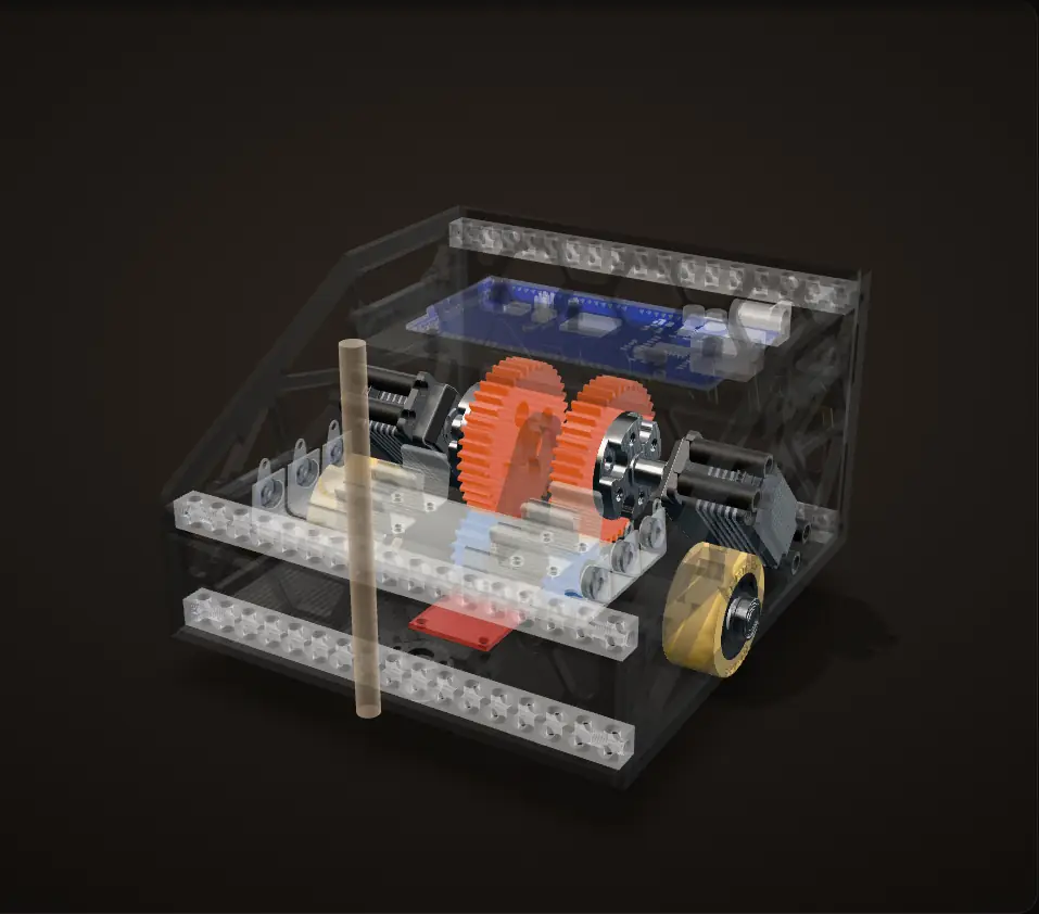
Two mirrored drive modules
Each side of the robot is a self-contained drive module, and the two are mirror images. The wheels sit in the middle of the robot's length, 120 mm apart, with a ball caster ahead of them and one behind (from the CAD).
One module: 2.5 to 1
An Axon MINI servo, run as a continuous-rotation motor, turns a 40-tooth spur gear on its output hub. That drives a 16-tooth gear on a 6 mm axle, so the wheel turns 2.5 times for every turn of the servo. The wheel is a 1-3/8 in BaneBots wheel on a BaneBots hub.
The axle
Cut along the axle: the 6 mm axle runs in two flanged ball bearings, one in the outer side plate just outside the wheel and one inboard of the 16-tooth gear. The wheel and the gear both sit between the two supports instead of hanging off the end of a shaft, and the wheel turns inside a window in the side plate (from the CAD).
Turning in place
Both wheels the same way drive straight. Opposite ways, the robot turns in place about the middle of the axle, the point my code steers. A quarter turn is each wheel rolling 94 mm, a quarter of the circle through both wheels (from the CAD).
Iterations
Dec 2024
Version 1: belted
In Fusion 360 by December 23, printed and assembled on the 24th, wired and driving on foam tiles by the 29th. GT2 belts at 3 : 1. My first code measured each wheel's distance from an angle signal on each drive.
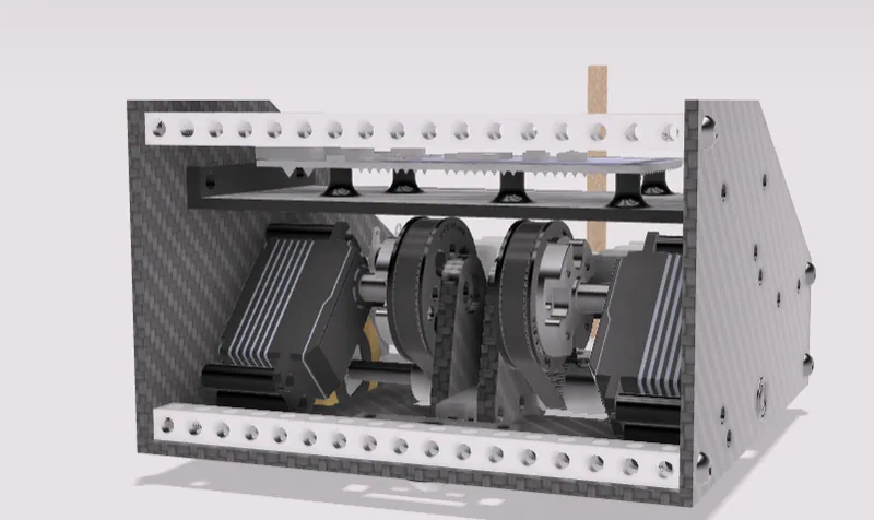
My render of version 1 from the front 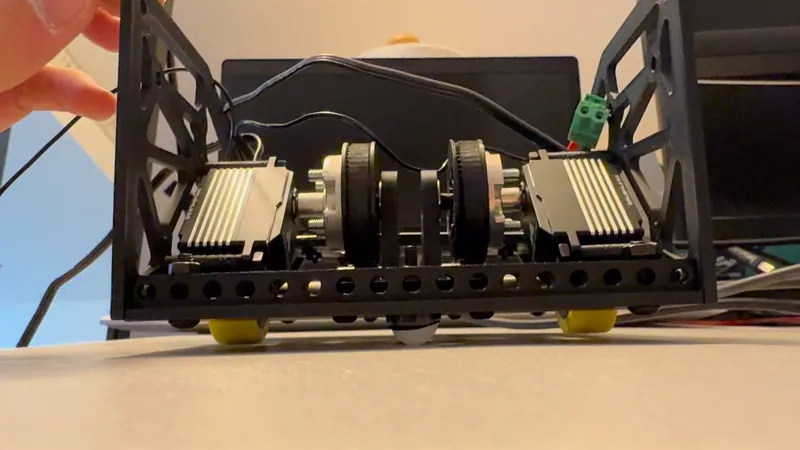
Version 1 from the front, Dec 29: both servos and their belts 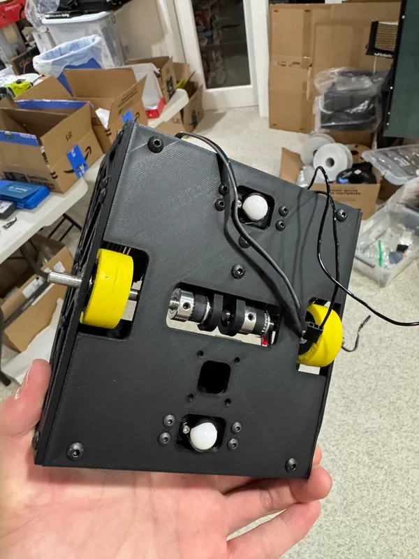
Version 1 from below: both casters, the wheels, the small pulleys through the slot, and the square window for the OTOS, still empty Mar 2025
Version 2: geared
Spur gears at 2.5 : 1 on the same centres, and a pointed nose on the bottom plate that holds the dowel. The OTOS is in both CADs, and its window is already in the version 1 bottom plate; by the end of March it was installed and running.
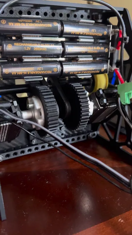
Version 2: the gear drive, under the battery cells 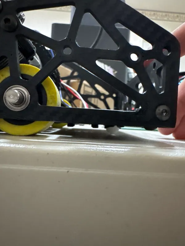
Version 2: a wheel in its window in the side plate 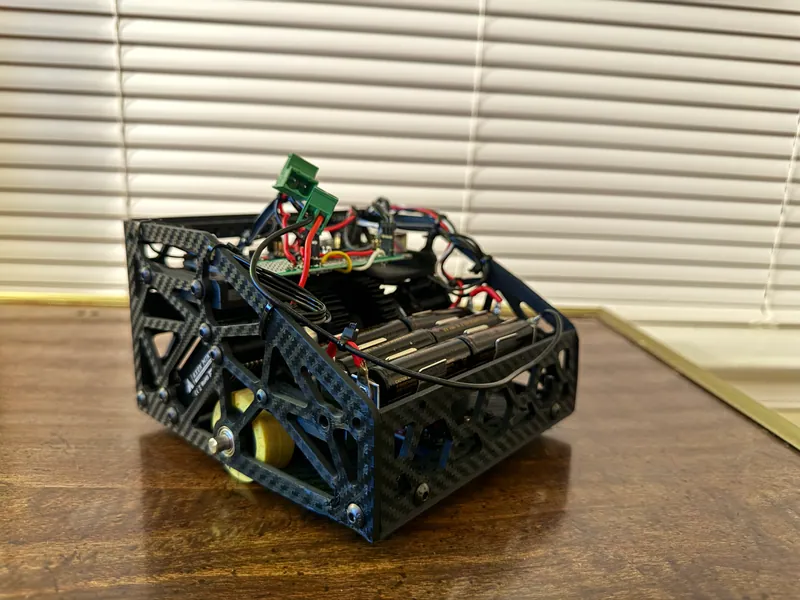
Version 2 Dec 2024 to Apr 2025
Software
First, wheel-by-wheel distance control from the angle signals. Then position and heading from the OTOS. Then a route of chained moves that carries each move's leftover error into the next.
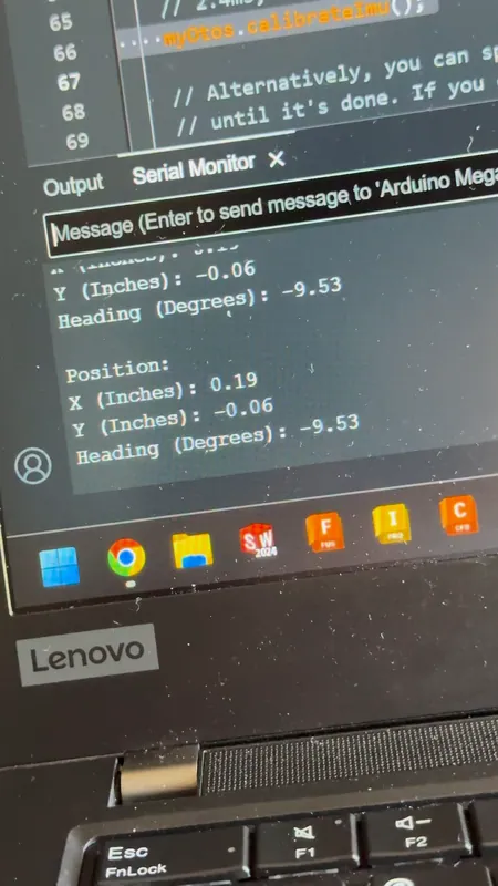
Bringing up the OTOS: its position in inches and its heading on the Serial Monitor


Belts to gears
Version 1 and version 2 of my CAD on one stage. They share one frame of reference, so everything that did not change stays exactly where it was.
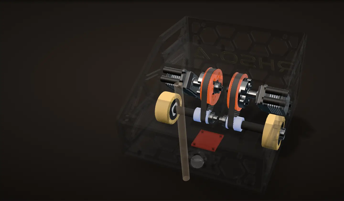
Version 1: belts
My first version drove each wheel with a GT2 belt: a 60-tooth pulley on the servo hub, a 20-tooth pulley on the axle and a 150 mm belt between them, so the wheel turned 3 times per servo turn. I chose belts because I thought they would have less backlash than gears.
The problem
Problem Friction in a printed frame
The belts had a lot of friction. The frame was all 3D printed, so the pulleys were not perfectly aligned with each other, and that caused problems.
The centres were fixed at 33 mm with no tensioner, and each 60-tooth pulley turned on a short shaft that ran in a third bearing in the printed frame (from the CAD).
Gears on the same centres
Fix Spur gears
I converted the drive to spur gears: a 40-tooth gear on the servo hub driving a 16-tooth gear on the axle, 2.5 : 1.
The gears have a module of about 1.18 mm (49.5 mm across the tips of 40 teeth), which puts 40 and 16 teeth exactly on the belt's 33 mm (from the CAD). The servos, the axles and their bearings stayed where they were; only the parts between them changed, and the third bearing and the pulley shaft are gone.
What changed at the wheel
Here both servos turn exactly once. Version 1's wheels turn 3 times and version 2's 2.5 times: for the same servo speed the geared drive is 17% slower at the wheel and gives 20% more torque (from the tooth counts). In the code it is one constant,
gearRatio, which went from 3.0 to 2.5.
Both versions are my CAD, drawn in the same place. Wheel turns and distances follow from the tooth counts and the 1-3/8 in wheel.
What the robot knows
How the robot measured where it was: first by counting wheel turns, then with an optical sensor looking at the floor.
First: counting wheel turns
My first code measured distance from an analog angle signal on each drive, read on the Arduino's A0 and A1: 0 to 3.3 V for one turn, on the servo side of the gears. The code multiplies the angle by the gear ratio, handles the jump from 360° back to 0°, and adds up the distance each wheel has rolled. A turn was each wheel rolling 8 cm in opposite directions (a comment in the code says it started at 9.58 cm).
Then: the OTOS
The final robot knows where it is from a SparkFun Optical Tracking Odometry Sensor on its underside. It watches the floor like an optical mouse, combines that with its own gyro, and reports x, y and heading directly, instead of the code working them out from wheel turns. It is already in the version 1 CAD, and the version 1 bottom plate has its square window. It sits on the centre line, 11.5 mm above the floor (from the CAD).
Its offset
The OTOS sits about 30 mm ahead of the wheel axis, turned 90°. When the robot turns in place it spins about the middle of the axle, so the sensor swings around a circle, and the dowel, 80 mm ahead, around a bigger one. The code tells the sensor both numbers,
setOffset({0, 0.0303 m, -90°}), so what it reports is the position of the turning point, not of the sensor.
The code
The code is on GitHub: 23 Arduino sketches, from the first servo test to the final route.
A route is a list of moves
The track layout is only announced at the event, and the program can be changed during setup. So my route is a list of simple moves, FORWARD_50, TURN_LEFT, FORWARD_100 and so on, with comments for the gate zones. A state machine runs them one at a time and moves on when a move reports that it is done.
Distance and heading control
In the final version each forward move runs two controllers off the OTOS: one on the distance left to go, one on the heading error. The wheel commands are the distance output plus and minus seven times the heading output, so the robot steers while it drives; in the last centimetre it stops steering. Turns use the heading controller alone, with the wheels turning opposite ways. A straight move is done within 1.5 mm and a turn within 0.5°, and the wheel commands are capped at 20% of full speed. Both controllers are PID controllers with only the proportional gain set; earlier versions also used a small derivative gain.

Calculation How fast can the geared version drive?
| Servo speed, no load | 0.080 s per 60° at 7.4 V | Axon MINI datasheet |
|---|---|---|
| Battery | six 1.2 V NiMH AA cells, 7.2 V in series; 7.4 V is the nearest rating | my photos |
| Gears | 40 teeth on the servo, 16 on the axle | my CAD |
| Wheel | 34.9 mm across (a 1-3/8 in BaneBots wheel) | my CAD |
- Servo: 60° in 0.080 s is 750° per second, 125 rpm
- Wheel: 125 rpm × 40 / 16 = 312.5 rpm, turning the other way from the servo
- Speed: 312.5 rpm / 60 × π × 34.9 mm = 0.57 m/s
About 0.57 m/s flat out. My code caps the wheel commands at 20% of full, so every move ran well below that.
A no-load maximum from the datasheet and the CAD, not a measured speed: under load, and at 7.2 V, it is lower.
Servo deadband
A continuous-rotation servo does not move until its command is a little way past stop, and each of mine needed a different amount in each direction. The code adds an offset per wheel and per direction to every non-zero command: in the final version 2.1% and 4.3% of full command for the left servo forward and backward, 0% and 6.5% for the right.
Problem Small errors add up
Every move ends a little off, up to the code's tolerances of 1.5 mm and 0.5°. If each move just started from wherever the last one stopped, those errors would add up over 45 moves.
Fix Carry the error into the next move
When a move finishes, the code works out where the robot is relative to where it should have ended: the sideways error, the along-track error and the heading error. It resets the OTOS so that its origin is the point where the robot should be, and its reading is the robot's error from that point. The next forward move aims straight at its ideal end point from wherever the robot actually is: its distance target is the straight-line distance there, and its heading target is the direction to it. Every waypoint is measured from where the robot should be, not from where it happened to stop.

Calculation How big could the errors get if they were not carried forward?
| Turn done within | 0.5° | my code |
|---|---|---|
| Straight move done within | 1.5 mm | my code |
| Final route | 45 moves: 23 turns and 22 straight moves | my code |
| Distance Score | 2 points per cm | the 2025 Robot Tour C rules |
- Worst case, every turn off the same way: 23 × 0.5° = 11.5° of heading error by the end
- One 50 cm leg driven 11.5° off: 50 cm × sin 11.5° = 10 cm to the side
- Every straight move short the same way: 22 × 1.5 mm = 3.3 cm along the route
Left alone, errors the code accepts as done could stack to about 10 cm to the side over a single 50 cm leg, 20 points. Carrying each error into the next move keeps them from stacking.
Worst case with every error the same way; real errors partly cancel.
Forward only
My first route, on the angle-signal code, backed out of gate zones and drove some legs in reverse: 8 of its 38 moves were reversing. The final route never reverses. It turns around in place instead, and the backward move is marked "DO NOT USE" in the final code.

A run through the example track
The example track printed in the 2025 rules, and my final coded route through it. As you scroll the robot drives the route, and the panel shows what it knows at each moment, worked out with my code's own formulas.
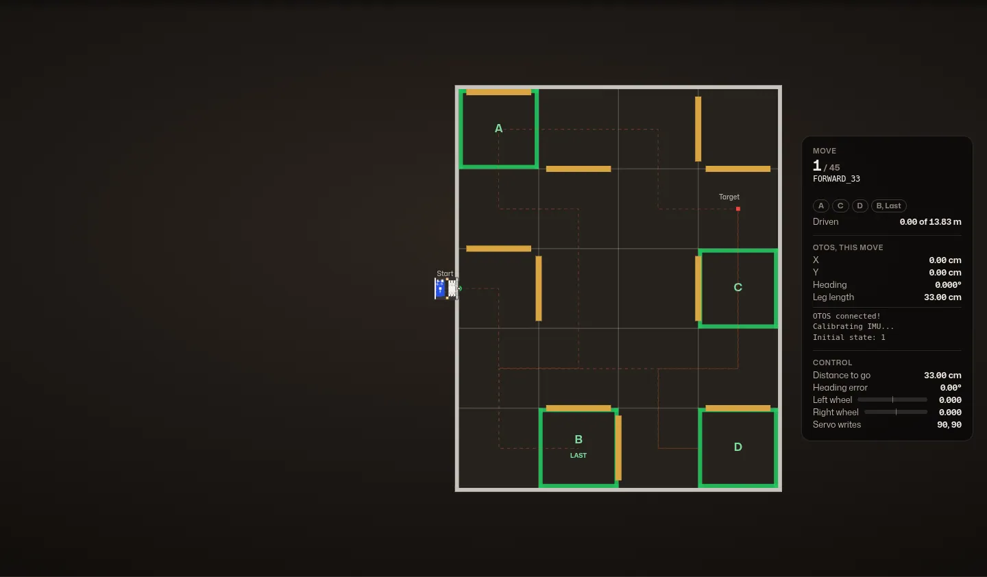
The track
Twenty 50 cm zones, ten 2x4s, gate zones A to D with B marked "Last", and the target point. The robot starts outside the left edge with its dowel over the start point. My final code has a route for this track: 45 moves, 23 turns and 13.83 m of straight driving.
Moves 1 to 11: gate zone A
The robot drives 33 cm into the track, then works its way around the 2x4s and up to gate zone A in the top left corner.
The panel shows the move the code is on; what the OTOS reads, reset after every move so Y climbs from zero along each leg; the errors each controller sees; and the two wheel commands after the deadband offsets and the 20% cap, with the servo values the code writes.
Moves 12 to 25: gate zones C and D
Across the top, through the target cell, down through gate zone C and over to the bottom right corner. Gate zone D is a dead end: the route drives 25 cm toward it, which puts the dowel, 8 cm ahead of the wheels, inside the zone, and turns around. The rules count only the dowel.
Moves 26 to 36: gate zone B, "Last"
Back along the bottom rows and into gate zone B from the side, after the other three, which is what the "Last" bonus asks for.
Moves 37 to 45: the target
Out of B, along the second row from the bottom, and up through C again. The last move is the one my code labels "to target".
What the robot does not know
Everything on the panel is the robot's own estimate. Carrying the error forward keeps that estimate on the route, but it can only correct what the OTOS reports. If the sensor drifts, the robot follows its wrong estimate perfectly and ends up somewhere else. The grey path shows that, exaggerated so it is visible.
Simulated from my final code: the route, the gains, the tolerances, the deadband offsets and the speed cap are from the code, and the track is the example in the 2025 rules. The motion is a simple model: the pacing follows the gains (full speed at the cap, then slowing in proportion), and each move ends with a small made-up error inside the code's tolerances. The robot is a top-down render of my CAD. The grey path in the last step is an illustration, not a measurement.
Testing
I tested on a taped practice grid on the hardwood floor at home, with a sticky note marked "START". I filmed single moves from above (one cell forward, a quarter turn, a straight lane) and whole chained routes.
The drift
Problem The OTOS drifted
The OTOS was not accurate enough. Its readings drifted over time, and the accumulated error pulled the robot's position estimate away from where it actually was. Carrying the error forward could not help with that: it cancels the robot's own mistakes only as well as the sensor sees them. A sensor that drifts sends the robot, confidently, to the wrong place.
In my recording of the robot sitting still, the position holds at 0.19 and -0.06 inches while the heading reading creeps from -9.41° to -9.53° over 21 seconds.
Calculation What does the OTOS's rated error cost on a track?
| OTOS error | typically 3 to 5 % out of the box, under 1 % calibrated | SparkFun OTOS |
|---|---|---|
| Start point to target point, example track | 175 cm across, 50 cm up | the 2025 Robot Tour C rules |
| Distance Score | 2 points per cm | the 2025 Robot Tour C rules |
- A sensor that reads every distance a fixed fraction long or short puts the end point off by that fraction of the straight line from start to finish, however long the route: √(175² + 50²) = 182 cm
- 3 to 5 %: 5.5 to 9.1 cm off, 11 to 18 points
- Under 1 %: under 1.8 cm, under 4 points
A scale error alone costs 11 to 18 points on this track out of the box, and under 4 once calibrated; heading drift adds to it, and its cost grows with every leg driven.
Estimate: a uniform scale error with the heading exact. The rated figures are SparkFun's, not measured on this robot.
Next time Next time: sensor selection
Sensor selection. The OTOS datasheet lists its drift, but I assumed it would not matter much over a Robot Tour run, and it did. With wheels this grippy, the motor encoders and an IMU alone would have tracked the robot better.
It would also have been interesting to try some form of SLAM.
More pictures


