← All projectsMIT Lincoln LaboratoryJul to Aug 2025
Hybrid Detachable UAV-UGV
Drone and ground rover docking system
A drone and a ground rover that dock together, so each one can carry the other.
A drone and a ground rover that lock together, so either one can carry the other. I came up with the project, recruited and led a team of seven, and designed and fabricated all of the hardware.
The core of it is a latch on the rover that catches the drone’s landing tubes with no power and lets go on command: a linkage geartrain with 10 axes of rotation, 6 of them driven by a single servo. On the course run the drone carried the rover, let go of it with the servo and flew on alone. I presented the work as first author at the IEEE MIT Undergraduate Research Technology Conference.
One full cycle, on my CAD
Both vehicles from my CAD. Scroll to see what is where, cut the rover open, and run a whole cycle: the drone carries the rover, lets go with the servo, and comes back to a latch that catches it with no power.
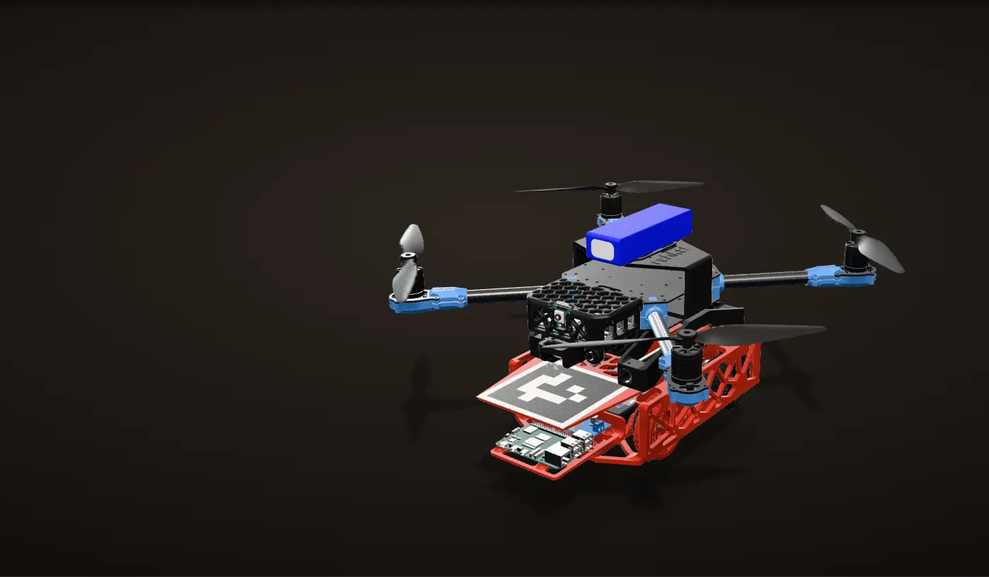
Two vehicles, one system
The drone sits on the rover with its two landing tubes held in the rover’s two latches. Docked, the rover can carry the drone across open ground, and the drone can lift the rover over what the rover cannot drive.
What is where
The drone’s printed landing gear holds a pair of 16 mm tubes 110 mm apart. The two latches sit on the rover’s deck, one per tube, with an AprilTag in front of them for the drone’s downward camera.
Inside the rover
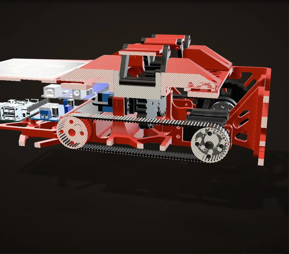
A cut along the centreline takes the rover’s left half off; hollow dots mark parts inside the chassis. The latch servo, a Feetech FT5325M, sits under the deck between the two latches. A Raspberry Pi 5 and an Arduino Mega ride in the middle, powered from a 2S 2200 mAh LiPo, and two Axon MINI drive servos sit inboard of the rear wheels.
The drone carries the rover
Latched, the rover hangs from the drone’s tubes. The doors hold them without the servo doing anything: pulling up only presses the tubes into the undersides of the doors. In the flight cage the drone lifted the rover and flew it across the cage.
Let go on command
The servo turns 11.8 degrees, the geartrain swings every arm 42 degrees, and the doors ride out on the arm tips, clear of the tubes. The drone lifts straight out and the latch closes behind it. On the course run, the servo let the rover go this way and the drone flew the course alone.
Coming back: a catch with no power
As the drone comes down, its tubes push the four doors down and out of the way. Once the tubes are down in their cradles, elastic pulls the doors back up over them, and the pair is latched again with no help from the servo. The next sections go inside each of these mechanisms.
The latch angles are from my CAD, and the door angles during the catch come from a section of the real door turned against the tube. How high the vehicles lift is an illustration. The elastic is drawn in; it is not in the CAD. The doors are shown as modelled, before I cut them to overlap (see the iterations below).
Why dock a drone to a rover
Drones get somewhere fast and see from above. Ground robots last longer on a charge and work at ground level. Each one is weak exactly where the other is strong, so I wanted one system that could be either.
Problem Two weak spots
A drone’s battery runs out quickly, and a ground robot gets stuck on terrain it cannot drive over.
Fix
Dock them. The rover carries the drone across open ground so the drone saves its battery. When the rover reaches something it cannot cross, or we need a view from above, the drone lifts off, on its own or carrying the rover with it.
We framed it as a cooperative multi-agent system for search and rescue and data collection.
The drone is a Holybro X500 V2 quadcopter on a 5000 mAh battery. I designed new 3D-printed landing gear for it: two mounts that hold a pair of 16 mm tubes 110 mm apart, and those tubes are what the rover grabs. The rover is a 3D-printed truss chassis, 327 mm long and about 1.23 kg, with two latches on its deck, one per tube, and an AprilTag in front of them for the drone’s downward camera.

The latch: ten axes of rotation, one servo
The latch has two jobs: catch the drone by itself, and let go on command.
Problem Weight
Every gram of latch is a gram the drone has to lift when it carries the rover, and a latch with a motor per arm or per door would be heavy.
Fix
I built both jobs into one linkage geartrain with 10 axes of rotation: 6 driven by a single servo, and 4 passive.
Calculation How heavy is the rover for this drone?
| Rover weight | 1.23 kg | weighed on a scale |
|---|---|---|
| Holybro’s rated maximum payload for the X500 V2 | about 1 kg, with a 4S 5000 mAh battery at 70 % throttle | Holybro X500 V2 specs |
- 1.23 kg / 1 kg = 1.23
- 1.23 kg - 1 kg = 0.23 kg over the rating
The rover alone is about 1.2 times the payload Holybro rates the X500 V2 for, so carrying it means flying above the 70 % throttle that rating assumes. Every gram in the latch adds to that.
Holybro’s figure is for its stock kit, not our drone with its printed landing gear.
Each latch has two arms that stand up on either side of a landing tube, with a door hinged on the tip of each arm. Front and back cradle brackets with a 17 mm bore locate the 16 mm tube before the doors ever close over it.
The geartrain drives all four arms from one Feetech FT5325M servo:

- The servo turns a 25-tooth gear.
- That gear drives a 25-tooth idler and the 7-tooth pinion on one arm of the first latch.
- The idler turns the other way and drives the 7-tooth pinion on one arm of the second latch, so the two latches open as mirror images.
- On each latch the two arms mesh through their 7-tooth pinions 1:1, so they swing apart like a V.
Going from 25 teeth down to 7 multiplies the motion by 25/7, about 3.6, so 11.8 degrees at the servo swings every arm 42 degrees, far enough to carry the doors clear of the tubes. The servo drives six of the ten axes: the servo gear, the idler and the four arm pinions. The other four are the pins the doors hang on at the arm tips. The doors ride along with the arms, but nothing drives them on their pins: only a tube or the elastic turns them.
| Part | Teeth | At full open |
|---|---|---|
| Servo gear (on the servo horn) | 25 | 11.8° |
| Idler, on two F693ZZ bearings | 25 | 11.8°, the other way |
| Arm pinions (4) | 7 | 42° |
The same step up that gives the arms their swing has a cost: a little play at a 7-tooth pinion becomes a lot of play at the doors. That is the story of the iterations further down.
Inside the latch
A section through the middle of both latches, and the geartrain running as you scroll.
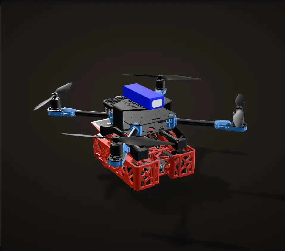
Two latches, one per tube
The drone sits on the rover with its two landing tubes in the two latches. The whole latch mechanism sits in one block behind the AprilTag.
A cut through the middle
The section runs through the middle of the arms. The tubes sit in the latches with the doors closed above them, and the geartrain is underneath.
One servo drives everything
The servo turns the 25-tooth gear. It meshes with the idler and with the 7-tooth pinion of one arm on the first latch. The idler drives one arm on the second latch, and each pair of arms is geared together 1:1.
11.8 degrees in, 42 out
The step from 25 teeth to 7 turns 11.8 degrees at the servo into 42 degrees at every arm. The arms swing apart like a V and carry the doors out past the tubes. The idler reverses the direction, so the two latches open as mirror images.
Let go
With the arms open nothing holds the tubes, and the drone lifts straight out. Carrying the rover, it is the same motion the other way round: the servo opens the arms and the rover drops out of the latch.
Six driven axes, four passive
The servo closes the arms again, ready for the next landing. The servo gear, the idler and the four arms turn on the six axes the servo drives. The four doors turn on their own pins at the arm tips, with nothing driving them, and they are what catches the drone.
Passive latching: elastic on the knobs
The four doors do the catching, with no power. Here is the first latch in section as the drone comes down onto it.
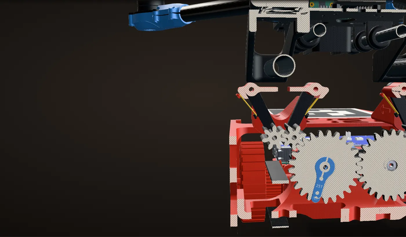
Doors held up by elastic
Each door hangs on the pin at the tip of its arm. Elastic stretched between a knob on the door and a knob on the arm holds the door up. The drone starts 32 mm above its docked position.
The tubes push the doors down
When the drone comes down, its tubes meet the tips of the doors about 24 mm above the docked position (in my CAD) and push them down and out of the way, stretching the elastic. A door has to swing about 42 degrees to let a tube past.
Past the doors, they snap shut
About 2 mm before the drone is fully down, the tube is past the doors, and the elastic pulls them back up over it. The drone is now held without the servo doing anything.
Pulling up only holds it tighter
Pulling up only presses the tubes into the undersides of the doors. In my CAD the drone can rise about 7 mm before the tubes meet them, and from there it is held.
Let go
To let go, the servo swings the arms out and the doors go with them, so nothing is left over the tube and the drone lifts straight out. Then the arms close again, ready for the next landing.
Door angles come from my CAD: a section of the real door turned on its pin against the 16 mm tube. As in the animation above, the elastic is drawn in and the doors are shown before the overlap cut.
The belt drivetrain
The rover’s left side, cut open along the outside of the belt. The wheels turn as you scroll.
Skid steered, one servo per side
The rover is skid steered. Two Axon MINI servos, one per side, sit inboard of the rear wheels and drive them through printed hubs. I reused the servos and hubs from my Science Olympiad Robot Tour robot.
One belt per side, 1 : 1
Each rear wheel has a 35-tooth HTD 3M pulley built into it, and a 384 mm long, 12 mm wide belt carries the drive to the same pulley inside the front wheel, about 140 mm ahead. Both wheels on a side turn together, 1:1. The wheels are 70 mm across.
Steering by speed
There is no steering linkage: the rover turns by running one side slower than the other. Here the left side runs at 30 % and the right at 70 %, so it arcs to the left. The inset is ideal skid steering, with no slip.
Turning in place
Run the two sides in opposite directions and it turns on the spot. The terrain tests further down measured how fast it turns on six surfaces.
The belt in my CAD is one solid part, so its motion is shown with marks drawn on it, one per tooth. The speeds are for the picture; the inset is a diagram, not CAD.
Electronics and drive code
The electronics ride in the middle of the chassis: a Raspberry Pi 5 and an Arduino Mega, powered from a 2S 2200 mAh LiPo through an LM2596 buck converter. The latch servo sits under the deck, between the two latches.

The drive code on the Arduino Mega is a small state machine: an array of states (drive forward, turn left, stop) that it steps through, driving the left and right wheel servos for each one and printing every transition to the serial monitor. In the first bench test the turns were commented out of the sequence and the chassis was stood on end: forward, then stop.
Fixing the latch
Version 1
Module 1 gears: the teeth skipped
My first geartrain used fine red gears at module 1. I modelled it and drove the joints in Fusion to check that the arms swung the way I wanted, then printed it.
Problem Gears skipped
The module was too small. Once printed, the gears skipped.
Fix
Much bigger teeth: version 2 is the black coarse gear. The gears in my final CAD measure module 2, twice the tooth size of version 1.
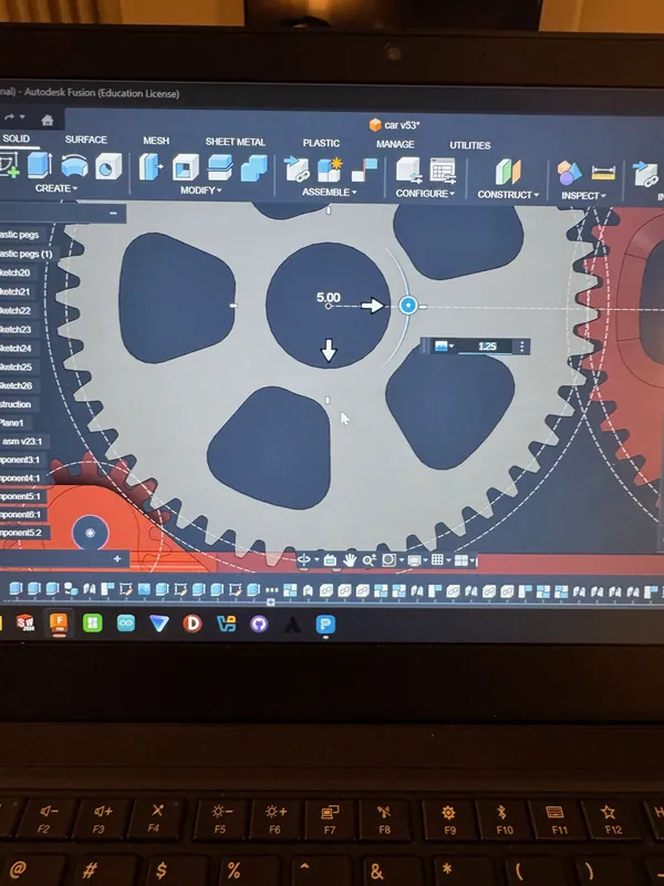
Version 1 in Fusion: the fine-pitch servo gear, Jul 25 Driving the version 1 geartrain in Fusion to check the arm motion 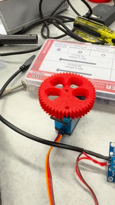
The first printed module 1 gear on the servo Version 2
Module 2 gears: no skipping, but backlash
I went into this change knowing what the bigger teeth would cost. Each arm hangs off a 7-tooth pinion, so a little play at the pinions becomes a lot of play at the doors on the arm tips. But backlash was something I could mitigate, and within our constraints there was no other way to stop the skipping. So I took the trade on purpose.
Problem Backlash at the doors
As expected, a lot of backlash, and it showed up at the doors: with that much play, they could not be counted on to close over the tube.
Fix
I dealt with it in the doors instead of the gears: I cut the doors so they would overlap each other.
Calculation How much play lets a door slip off the tube?
Arm pinion 7 teeth, module 2: 7 mm pitch radius measured from the CAD Pinion axis to the outer door’s finger tip 35.8 mm measured from the CAD How far each finger reaches past the tube’s edge 3.7 mm measured from the CAD Meshes from the servo gear to the outer arm of the first latch 2 counted from the CAD - When the arm turns, its finger tip moves 35.8 / 7 = 5.1 times as far as its pinion’s pitch circle
- For the finger to swing 3.7 mm off the tube: 3.7 mm / 5.1 = 0.72 mm of free travel at the pinion
- Play adds up along the chain: with play p at each mesh, the outer arm can drift p / 2 per mesh either way, p over two meshes. So p = 0.72 mm
- A module 2 tooth repeats every π × 2 mm = 6.3 mm, so that is about a ninth of a tooth
About 0.7 mm of play at each mesh, a ninth of a tooth, is enough to let the outer finger swing off the tube. The small pinion is the multiplier: on a 25-tooth gear (25 mm pitch radius) the finger would need 25 / 7 = 3.6 times as much play.
Geometry only, from the final CAD with the doors as modelled, before the overlap cut; the play in the real gears was not measured. The backlash section below shows the same numbers on the model.
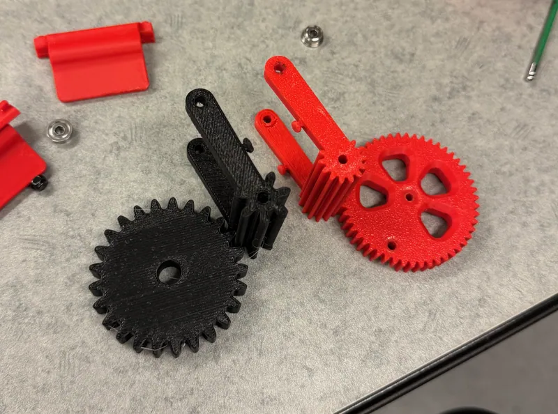
Version 1 (red, module 1) next to version 2 (black, module 2), each gear with an arm and its pinion, Aug 1 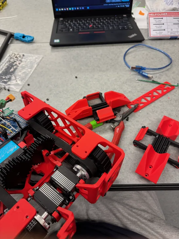
Latch assemblies, black arms and red doors, laid out next to the rover, Aug 1 The fix
Doors cut to overlap
Fix
On one latch the cut doors now overlap. On the other, because of the backlash, they barely close, but that is enough to close the latch around the tube.
The cut is not in my CAD, so the 3D on this page shows the doors as modelled, with a gap between them. The photos show the real, cut doors.
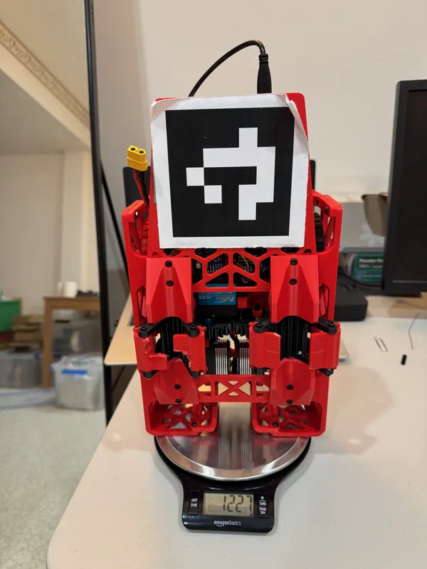
Weighing the rover, Aug 10: about 1.23 kg. Stood on end, it shows both latches: the left one’s cut doors overlap, the right one’s barely close 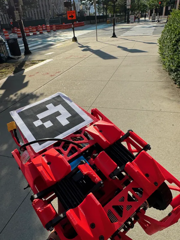
The latches on Aug 2, with the rough cut edges on the doors


Why backlash hurts this latch
The first latch in section, on the final CAD, with the doors as modelled (before the cut). The ghosts show each arm at both ends of its free play.
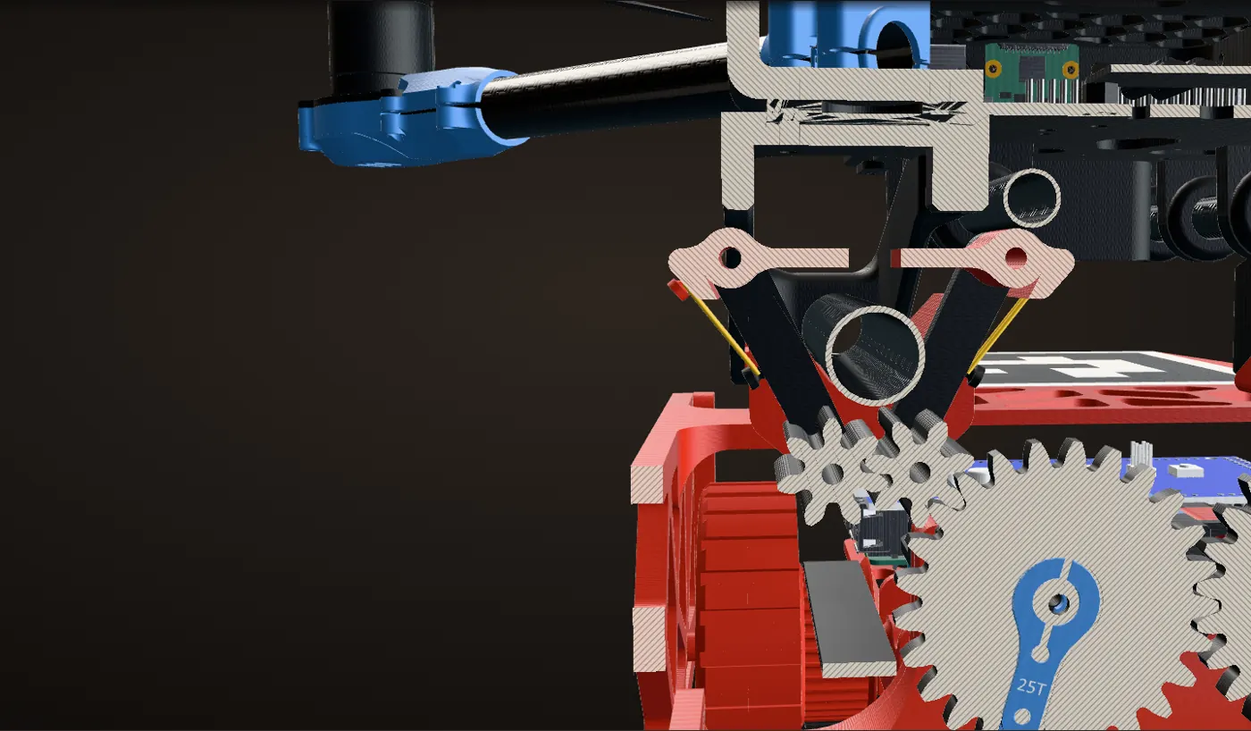
Play at a 7-tooth pinion
Play at a mesh, measured along the pitch circle, turns a 7-tooth pinion by the play divided by its 7 mm pitch radius. So 1 mm of play is 8.2 degrees at the arm, and a door’s finger tip sits about 36 mm from its arm’s pinion: about 5 mm at the tip.
Half a millimetre at each mesh
The ghosts are each arm at both ends of its free play, with 0.5 mm of play at each mesh. The arms can rock anywhere between them, and the doors ride along on the arm tips.
Play stacks up
Problem Play stacks up
The play also adds up along the chain. On the first latch the inner arm is one mesh from the servo gear and the outer arm is two. On the second latch the arms sit behind the idler, two and three meshes out. And in the CAD each door finger reaches only about 3.7 mm past the edge of the tube: about three quarters of a millimetre of play at each mesh is enough to swing the outer finger that far.
The fix went into the doors
Fix
The overlap cut on the real doors is what closes the latch around the tube despite the play: on one latch the doors overlap, on the other they barely close, and that is enough.
The cut is not in my CAD, so it is not shown here; the photos in the iterations above show the real doors.
The numbers are computed from the CAD geometry, not measured.
Build log
The project was self-initiated and went beyond the curriculum, using the lab’s drones and 3D printers. Dates are from the photos.


Testing and results
In the flight cage the drone lifted the rover and flew it across the cage, and the rover drove and turned with the drone riding on top: the first two videos at the top of this page.
On the course run, the docked pair lifted off together and the drone carried the rover onto the course. Then the servo opened the latch and let the rover go, and the drone flew the course on its own, through the gate, and came back down beside the rover.
Six terrains
We then tested the rover on six surfaces at a constant 8.0 V, three trials each. We timed straight runs over a meterstick with a stopwatch, and turns with a protractor and a timer.
Straight-line speed
In a straight line the surface hardly mattered: on every surface the rover could drive, it averaged between 0.57 and 0.63 m/s.
Concrete was the fastest
Concrete was the fastest in a straight line, at 0.63 m/s.
Turning: foam and concrete
Turning is where the surfaces split apart. The rover turned fastest on foam (4.20 rad/s) and concrete (4.05 rad/s). Those two are synthetic surfaces, so our poster’s text leaves them out and names sand as the fastest turning surface; the chart has all six.
Sand
On sand it turned at 3.40 rad/s, the fastest of the natural surfaces.
Forest floor
On forest floor the rover kept most of its straight-line speed but turned at 1.25 rad/s, less than a third of its rate on foam.
Grass
Problem Grass
The rover could not cross grass at all.
Fix
This is where the drone takes over: on terrain the rover cannot drive, the drone flies, alone or carrying the rover.
The data points to terrain-aware mission planning: on low-mobility surfaces like forest floor and mulch, deploy the drone more often; on smooth, fast ones like concrete, let the rover carry it.
Averages of three trials per surface, from Table 1 of our poster: straight-line speed (m/s) and turning speed (rad/s). Foam 0.62 and 4.20, concrete 0.63 and 4.05, grass could not cross, mulch 0.57 and 1.88, sand 0.60 and 3.40, forest floor 0.59 and 1.25.
Why turning split the surfaces
A skid-steered rover has no steering linkage: to turn in place, one side drives forward and the other backward, and all four wheels have to scrub sideways over the ground. How easily they scrub depends on the surface.
Calculation How close to an ideal turn did the rover get?
| Track width, wheel centre to wheel centre | 135.2 mm | measured from the CAD |
|---|---|---|
| Straight-line and turning speeds per surface | Table 1 | our poster |
| Each side’s wheel speed while turning | the same as in a straight line | assumed (same 8.0 V) |
- With no slip, turning in place with each side at speed v gives ω = 2v / 135.2 mm
- Foam: 2 × 0.623 / 0.1352 = 9.22 rad/s possible, 4.20 measured: 46 %
- Concrete: 9.28 possible, 4.05 measured: 44 %
- Sand: 8.85 possible, 3.40 measured: 38 %
- Mulch: 8.50 possible, 1.88 measured: 22 %
- Forest floor: 8.66 possible, 1.25 measured: 14 %
Even on foam the rover turned at under half of the no-slip rate, and on forest floor at about a seventh. Straight-line speed barely changed between surfaces, so where they differ is mostly in how easily the wheels scrub sideways.
Estimate: ideal skid steering with no slip is an upper bound; the measured rates are the poster’s averages of three trials.


Research
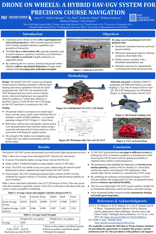
After the summer we ran more tests, collected more data and wrote the work up. I presented the poster “Drone on Wheels: A Hybrid UAV-UGV System for Precision Course Navigation” as first author at the IEEE MIT Undergraduate Research Technology Conference (URTC), October 10 to 12, 2025.
Authors: Jerry Li, Mihika Sakharpe, Zoe Zhao, Katherine Zhang, William Kollmyer, Shashwat Pandya, and Chris Rincon (PI). Read the poster (PDF).
The poster’s data is on this page: the terrain speeds (Table 1), the latch strength (Table 2), its photos of the docked pair in the air and the rover on forest floor, and the overall dimensions from its side view.


What comes next
Next time Better wheels
The rover could not cross grass, and our poster calls for better wheels on the ground vehicle alongside sending the drone over dense vegetation.
Next time Autonomous docking
The AprilTag is already on the rover for the drone’s downward camera. Closing that loop, so the drone finds the rover and docks on its own, was the next step we identified.
Next time Working as a team
Coordinating the two vehicles as a team (multi-agent integration), and SLAM so they can map together, were the other next steps we identified.