← All projectsPersonal projectFeb to Aug 2024
Replac3d
Automatic 3D printer build plate changer
A robot that swaps finished build plates for fresh ones so a 3D printer can run around the clock.
My FTC team’s 3D printer sat idle every night, because someone had to be there to pull each finished print. Replac3d reaches into the printer, pulls the build plate out with four electromagnets, parks it on a holder and loads a fresh plate from a second holder, so the next job can start with nobody there.
I built it alone from February to August 2024. It took our usable print time from about 7 hours a day to 24. It was my first personal technical project: I had no electronics experience going in and learned steppers, drivers, soldering and firmware on it.
One swap, step by step
Scroll to run a full swap on my CAD. Everything happens on two axes: a turntable, and an arm that rides on it and reaches out.
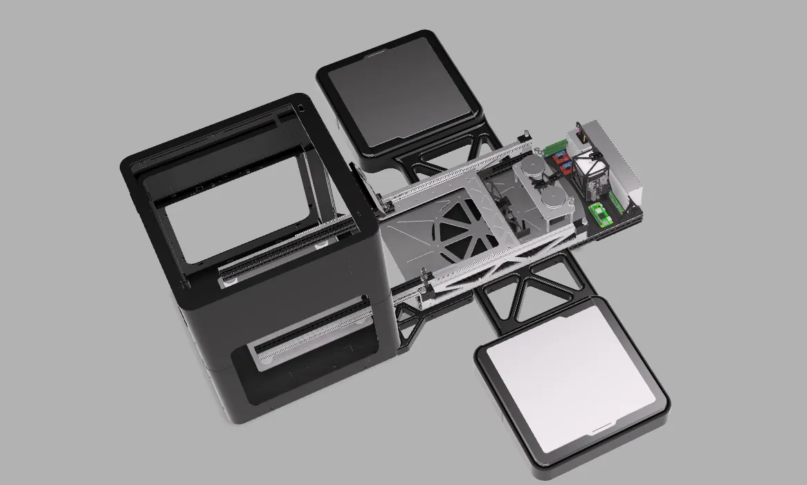
A print finishes
The printer sits behind the robot, a plate holder on each side: a fresh plate on the left, the right one empty. At the end of a print the bed drops to the bottom and the plate presses a button that starts the swap.
Reach in
Two NEMA 17 steppers pull belts that run the carriage 355 mm into the printer on a pair of telescoping ball slides. The printer goes see-through so you can watch.
Grab
Four 5 V electromagnets, switched by two MOSFET modules, take hold of the steel plate from above.
Slide it off the bed
The arm pulls back. The plate slides forward off the bed, print and all, and comes out with it.
Turn to the empty holder
A NEMA 23 swings the whole arm 90° through a 3.6 : 1 belt reduction.
Park the used plate
The arm reaches out over the holder, the magnets let go, and it pulls back empty.
Turn to the fresh plate
180° to the other holder.
Pick up a fresh plate
Reach out, magnets on, pull back with a clean plate.
Turn back
90° back to the printer.
Load it
The arm reaches in, sets the fresh plate on the bed, lets go and pulls back. The printer is ready for the next job.
My CAD, without its screws and nuts. The printer’s bed is not modeled, so only the plate moves with it. The belts are not in the CAD either: they are drawn along the path its pulleys, idlers and clamps set, and glow while they drive the arm. The readout names the function of my final sketch that each move belongs to. The finished print on the used plate is 3DBenchy by Creative Tools.
Why take the whole plate out
We could only run the printer from 3 to 10 PM, because someone had to take each finished plate off and start the next job. A print that finished in the evening left the printer idle until the next afternoon. I wanted a machine that does that one human step.
I researched how other people automate a printer, and none of the approaches fit mine, a Bambu Lab P1S:
| Approach | Why I passed on it |
|---|---|
| Push the print off with the toolhead | Fails on short prints, can damage the part and the toolhead, and the part has to be caught out of the air |
| A conveyor of build plates | Only works on printers a plate can pass through, which rules out the P1S, and the plate still falls |
| Scrape the print off | Can damage the print and the plate, large prints can tip over, and small things like brims get missed |
| A plate changer that grips the plate at its edge | The one I found was far too large, and a plate held at its edge can bend under a heavy print and drop it |
So Replac3d lifts the whole plate out, print and all, and puts a fresh one in. It holds the plate from above with four electromagnets, strong enough to beat the magnet in the printer’s bed.


From linear rails to drawer slides
My first concept in February put the magnet plate on two MGN12 linear rails. The plate was bolted to the rails’ carriage blocks at its back end and reached forward over the printer plate. I ran FEA on the grasper plate in Fusion 360 before cutting anything.
Problem The rail concept
Reach, footprint and cost. In the concept CAD, 450 mm rails carry the magnet plate 405 mm forward, and at full reach the plate hangs about 400 mm past the ends of the rails, held only at its back by two small blocks. Precision rails also cost a lot for accuracy this job does not need.
Fix
Off-the-shelf telescoping drawer slides, one on each side of the carriage. They fold the reach back into the frame, they are cheap, and they are precise enough to set a plate down. By the time parts arrived in March the design had become a turntable carrying those slides, so one arm could serve the printer and two holders.
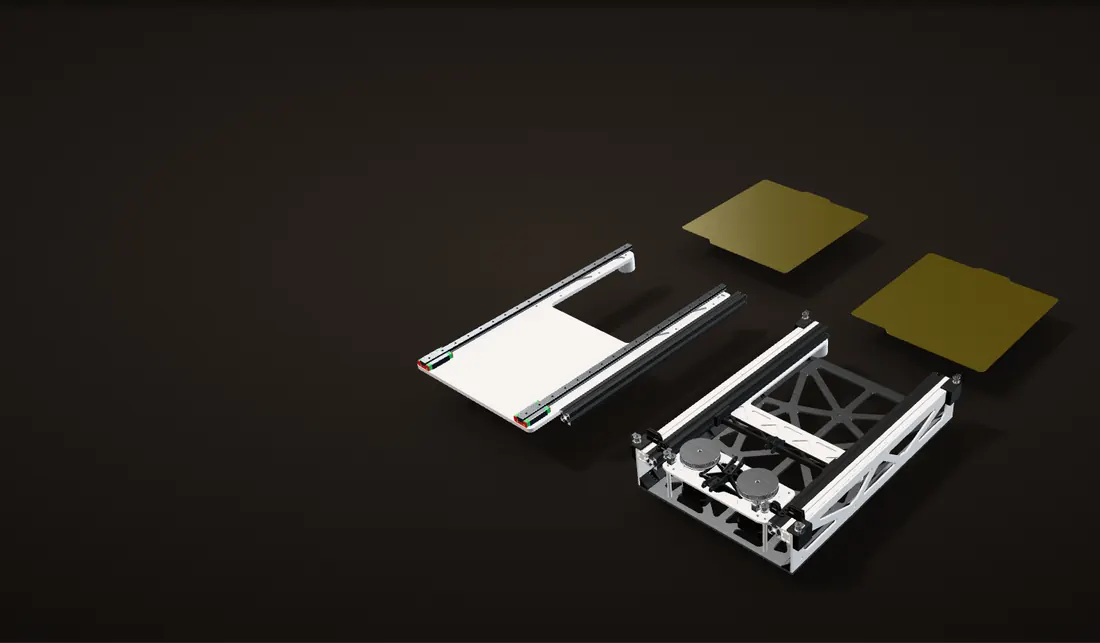
Side by side
My February concept (left) and the final arm (right), from my CAD at the same scale. The concept bolts the magnet plate to the blocks of two 450 mm MGN12 rails; the final carriage rides a 400 mm telescoping slide on each side.
The same job
Both reach out over the printer plate. The concept’s blocks and plate slide the full length of its rails, 405 mm; the final carriage runs its 355 mm stroke.
Held only at one end
From the side: at full reach the concept’s plate hangs about 400 mm past the ends of its rails, held only at its back by the two small carriage blocks (orange).
Carried along both sides
The final carriage is carried by a slide on each side along its whole length (the slides’ middle members, blue).
Folded back in
Pulled back, the final arm folds its whole reach into the frame, so it can turn between the printer and the two holders.
Both from my CAD, at the same scale, run through their reach by the scroll.
The telescoping arm
The arm has to reach 355 mm into the printer and fold back into a 400 mm frame so it can turn.
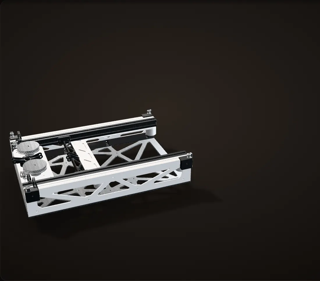
Folded into the frame
Each side runs on a MISUMI SAR340, a 400 mm, three-member aluminum ball slide: the outer member bolted to the side plate, the inner member to the carriage’s 2020 extrusion, the middle member riding between them.
Inside a slide
Cut through the upper balls. Each row of balls rolls at the mean speed of the two members around it: as the carriage moves out, the middle member goes half as far, the two ball rows three quarters and a quarter as far.
Two open belts
Each side has its own NEMA 17 at the back of the frame and its own GT2 belt. The belt is open, both ends clamped to the back of the carriage: as the motor turns, one run shortens, the other lengthens, and the carriage moves.
Out to 355 mm
In the CAD each motor has an 80-tooth GT2 pulley, which moves 160 mm of belt per turn: the full 355 mm stroke is about 2.2 motor turns.
Back in
The motors turn back and pull the carriage home, and the slides fold back into the frame.
From my CAD. In a real slide the middle member floats between its stops; here it is drawn at half travel. Each belt runs from one clamp forward to a GoBILDA idler at the front of the frame, back along the outside of the slides, across the back, round the motor pulley and the two idlers beside it, and forward to the other clamp. The belts are not in the CAD: they are drawn along the path its pulleys, idlers and clamps set, with GT2 teeth at a 2 mm pitch.
Speed, and which pulley
My final sketch drives the arm 14,000 steps for the full stroke, at up to 3,000 steps/s and 1,000 steps/s². Those numbers say how fast the arm moves, and which pulley they fit.
Calculation How fast does the arm reach out?
| Full stroke | 355 mm | measured from the CAD |
|---|---|---|
| Steps for the stroke | 14,000 | my final sketch |
| Top speed | 3,000 steps/s | my final sketch |
| Acceleration | 1,000 steps/s² | my final sketch |
- Travel per step: 355 mm / 14,000 = 0.0254 mm
- Top speed: 3,000 × 0.0254 = 76 mm/s. Acceleration: 1,000 × 0.0254 = 25 mm/s²
- Reaching top speed takes 3,000 / 1,000 = 3 s and 3,000² / (2 × 1,000) = 4,500 steps; speeding up and slowing down use 9,000 of the 14,000 steps
- One stroke: 14,000 / 3,000 + 3,000 / 1,000 = 4.7 s + 3.0 s = 7.7 s
About 7.7 s for each 355 mm stroke, and about two thirds of the steps are spent speeding up or slowing down. That gentle profile is on purpose: nothing re-homes the arm, so I kept speeds and accelerations low enough that the steppers would never skip and lose count.
Estimate for an ideal move at the sketch’s limits (a trapezoidal speed profile).
Calculation Which pulley do the step counts fit?
| Turntable to a holder | 1,440 steps for 90° | my final sketch |
|---|---|---|
| Turntable reduction | 288 : 80 = 3.6 | tooth counts from the CAD |
| Full steps per motor turn | 200 (1.8° a step) | 23HS30-2804S, the NEMA 23 in my CAD |
| TMC2209 microsteps | 8 with MS1 and MS2 low; 16, 32 or 64 otherwise | TMC2209 datasheet, 3.4 |
| Belt per pulley turn | 80 teeth: 160 mm; 20 teeth: 40 mm | teeth × 2 mm GT2 pitch |
- Turntable: 90° of the arm is 0.25 × 3.6 = 0.9 motor turns, so 1,440 / 0.9 = 1,600 steps a turn: 200 full steps × 8 microsteps
- Extension at the same 1,600 steps a turn: 14,000 / 1,600 = 8.75 motor turns
- With the CAD’s 80-tooth pulley: 8.75 × 160 mm = 1,400 mm, four times the stroke
- With a 20-tooth pulley: 8.75 × 40 mm = 350 mm, within 5 mm of the 355 mm stroke
At the turntable’s setting, 14,000 steps only fits a 20-tooth pulley: the change I planned for torque, since the speed was already sufficient (build log), and the photo beside this shows a small pulley on the motor. For the same motor torque a 20-tooth pulley pulls four times as hard on the belt (pitch radius 6.4 mm instead of 25.5 mm). The 80-tooth pulley would only fit if its drivers were set to 32 microsteps.
Assumes 1.8° extension motors and the same microstep setting on every TMC2209 on my perfboard. The CAD and the animations keep the 80-tooth pulleys.

The turntable
The turntable carries the whole arm, both extension motors and a plate held up to 355 mm out, so its bearing takes a large tipping load as well as the weight. I designed it from small off-the-shelf bearings, shown below from my CAD.
Problem Grinding
The first time I tested the turntable it made a loud grinding noise, and screws caught on each other because there was not enough room between the layers.
Fix
I rebuilt the bearing stack with new spacers and fastened the standoffs with different screws. After that it spun smoothly.

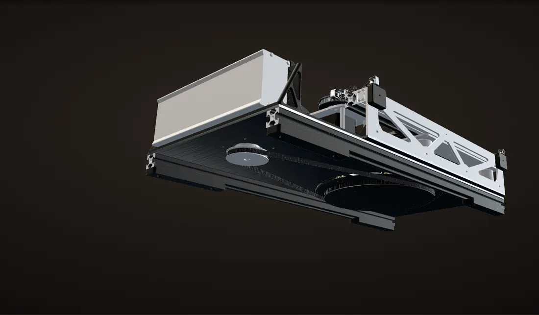
Seen from below
A NEMA 23 at the back of the base drives a printed pulley disc under the turntable, with an 80-tooth pulley and a GT2 belt.
A quarter turn
The disc has 288 teeth on its rim. That is a 288 : 80 = 3.6 : 1 reduction (tooth counts from the CAD), so a quarter turn of the arm is 0.9 of a motor turn.
The three stations
A swap only ever stops the turntable at 0° and ±90°. Going from one holder to the other is half a turn of the arm and 1.8 turns of the motor.
Pull the stack apart
A fixed middle plate with a 210 mm hole. The printed 288-tooth pulley disc sits under the hole, the arm’s bottom plate above it, and eight standoffs through the hole tie the two together.
Cut through one post
On each standoff, GoBILDA thrust bearings above and below clamp the middle plate (16 in all, for the weight and the tipping load), and an MR106 bearing rolls on the edge of the hole to keep the turntable centered.
From my CAD, seen from below, then close on one of the eight bearing posts. The motor pulley turns 3.6 times as far as the arm.


Electronics
Everything lives in two printed bays at the back of the base. I measured every board and the power supply with a ruler, modeled them in the CAD, and designed the bays around those models.
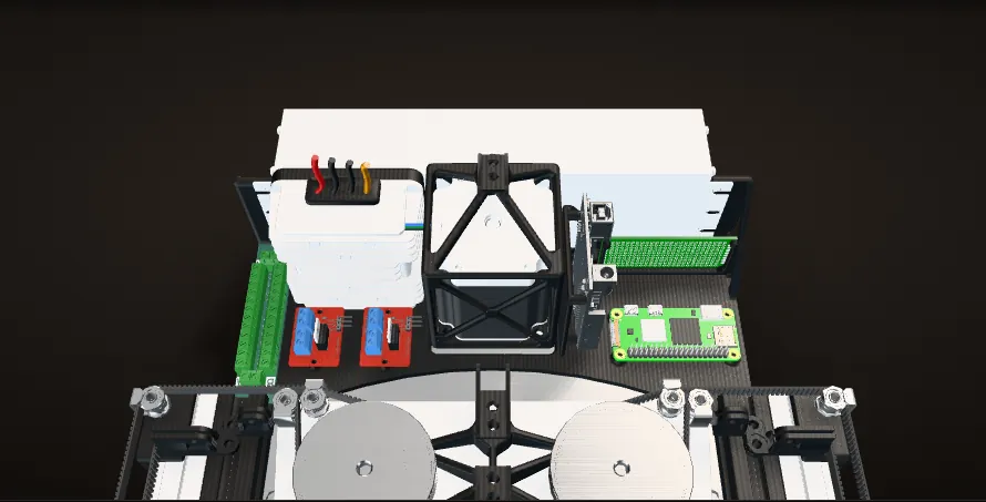
Two printed bays
Seen from the printer’s side. The Arduino Uno, my driver perfboard and the Raspberry Pi sit in one bay; the buck converter, the terminal block and the two MOSFET modules in the other.
Power
A 24 V, 250 W supply for the steppers and a 24 V to 5 V, 16 A buck converter for the 5 V side, shared out through a screw terminal block. One red rocker switch turns it all on.
Magnets
Two MOSFET modules, each switching two of the four 5 V electromagnets on the carriage.
Motion
An Arduino Uno and my own perfboard of TMC2209 stepper drivers: one for the turntable’s NEMA 23 and one for each extension NEMA 17.
Raspberry Pi Zero 2 W
Meant to tell the Uno when a print is done. That part was never finished (more under the firmware).
From my CAD. The stepper driver modules are not in it; the perfboard they plug into is. The tiny surface-mount parts on the boards are left out to keep it light.
Stepper drivers
Problem Fried drivers
I started with TMC5160 drivers and fried all of them with bad soldering.
Fix
I realized I did not need drivers that powerful and switched to TMC2209s. They also take plain step and direction pulses, with no SPI setup, which made the code simpler.

Problem Two motors, one axis
The two extension motors have to move exactly together. When I ran both from one driver it had problems I could not debug.
Fix
Each extension motor got its own TMC2209 (I added the third driver in August), and I wired both drivers to the same step and direction pins with separate enable pins, so the firmware drives them as one axis.


The firmware
The sketch that ran the swap in the video is one Arduino file, finalWorking08-23-2024.ino, on GitHub. It uses the AccelStepper library for two axes: panning for the turntable (up to 1,000 steps/s, 1,000 steps/s²) and extension for the arm (up to 3,000 steps/s, 1,000 steps/s²). A swap is four functions that follow one pattern: pull the arm in, turn, reach out, wait half a second, switch the magnets, wait, pull back.
The stations are hard-coded step targets: the turntable goes to -1,450, 0 or 1,440 steps and the arm to 0 or -14,000. runToNewPosition() blocks until each move is done, so only one axis moves at a time. That kept the code simple. It is also why the two extension motors are handled in hardware: both of their drivers listen to the same step and direction pins, and the sketch only switches their enable pins. The magnets are one output pin. In this version the whole sequence runs once from setup() when the board powers up.
Knowing when to start
Problem MQTT
The plan: the printer publishes “done” over MQTT, and the Raspberry Pi, subscribed, tells the Uno to start. I never finished it.
Fix
A hard-wired button: at the end of a print the bed drops all the way down and the plate presses it.
The button
Problem The button
In use, the plate often missed the button at the bottom. Knowing when to start was the main way the machine failed.
retrieve()At the printer: reach in, magnets on, pull out. The turntable is already at 0 steps, so only the arm moves.
deposit()Turn to the right-hand holder at 1,440 steps, reach out, magnets off, pull back empty. Each move blocks until it is done, so the turntable and the arm never move at the same time.
pickup()All the way across to the left-hand holder at -1,450 steps, reach out, magnets on, pull back with the fresh plate.
replace()Back to the printer at 0, reach in, magnets off, pull back. The printer is ready for the next job, and
loop()is empty.No homing
Problem Homing
No limit switches or other homing: I zeroed both axes by hand and kept speeds and accelerations low so the motors would never skip and lose count.
Step positions and the magnet pin as my final sketch drives them. Time runs left to right, worked out for ideal moves at the speed and acceleration limits set in the sketch.
The hard part: holding the plate
Getting the magnets to hold the plate every time was the hardest problem in the project. From the first magnet test in March to August, the grab was the weak point.
Problem Stock plates
The stock Bambu plates were too thin, and their PEI coating sits between the steel and the magnets. An electromagnet’s rated pull (10 kg for each of mine) assumes thick steel pressed right against its face, and a thin sheet behind a plastic coating is far from that.
Fix
I made my own build plates: 3 mm steel, laser cut by Fabworks in the same outline as the stock plate, so they fit the printer and my holders. The printer prints straight onto them, and pickup became 100% reliable.

Calculation Four 10 kg magnets for one steel plate
| Plate volume | 207.6 cm³ (258 × 276 mm, 3 mm thick) | measured from the CAD |
|---|---|---|
| Steel density | 7.87 g/cm³ | MatWeb, AISI 1008 sheet |
| Magnets | 4, rated 10 kg holding force each | Adafruit 3874 |
| Holding force to what it can pick up | divide by 5 to 10 | Adafruit 3874 |
- Plate: 207.6 cm³ × 7.87 g/cm³ = 1,630 g, about 1.6 kg
- Rated holding force: 4 × 10 kg = 40 kg, 25 times the plate
- What they can pick up by Adafruit’s rule: 40 kg / 10 to 40 kg / 5 = 4 to 8 kg, 2.5 to 5 times the plate
Even on ideal steel the margin is only 2.5 to 5 times, before the print adds its weight. Adafruit’s figures assume flat steel in full contact with the magnet; the stock plate’s steel is 0.65 mm thick in my CAD and sits under a PEI coating, which is why it would not hold reliably and the 3 mm plates did.
Estimate. The steel grade is unknown; plain carbon steels are all about 7.85 to 7.87 g/cm³. The plate alone, without a print.
Problem Too much friction
Once the magnets held, the steppers could not pull the plate out of the printer. They skipped.
Fix
Thick, clear, rubbery tape under each plate, about 3 mm of it, cut the friction enough for the steppers to pull it out.

How it got here
Feb 2024
Concept
Four electromagnets over a plate, then the magnet plate on two rails, checked with FEA before I cut any metal.
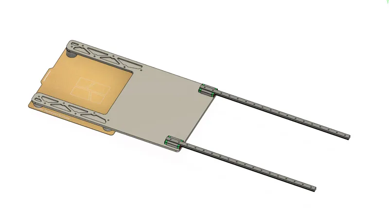
The rail concept in CAD (Feb 11, 2024) Mar 2024
Frame, turntable and slides
I cut the triangular pockets in the aluminum side plates on a CNC router. By March 14 the frame, turntable and slides were assembled, with a piece of cardboard standing in for a plate, and the extension belts went on over the next few days.
CNC pocketing a lattice side plate (Mar 8, 2024) 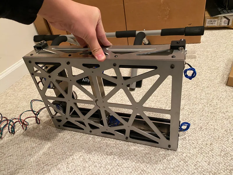
The lattice frame (Mar 13, 2024) 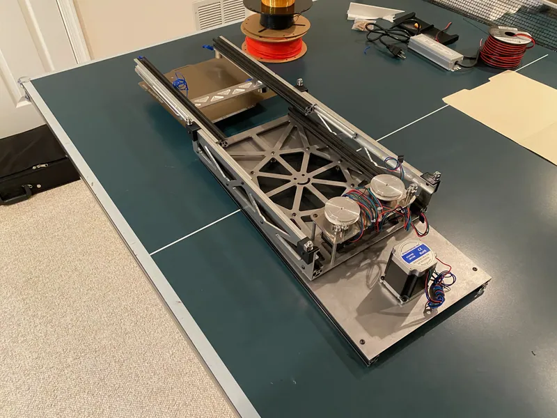
Frame, turntable and slides together for the first time (Mar 14, 2024) Mar to Apr 2024
Magnet tests
First magnet tests on a stock plate, then grab tests by hand inside the printer, before any motor drove the arm.
Problem
The stock plates would not hold reliably (see above). This stayed open until August.
An early magnet test on a stock plate, my hand underneath to catch it (Mar 28, 2024) Apr to Jun 2024
Drivers and the first powered moves
The first drivers were TMC5160s, which I fried. By June I had two TMC2209s on my own perfboard, and the arm ran automatic sequences: turn, reach out, pull back, turn back.
An automatic turn, reach and retract sequence, at 2x (June 2024) Jul 2024
Wiring, bays and the printer
Drag chains for both axes, printed chain mounts, the printed electronics bays and the power switch. On July 29 the arm drove into the printer under its own power for the first time.
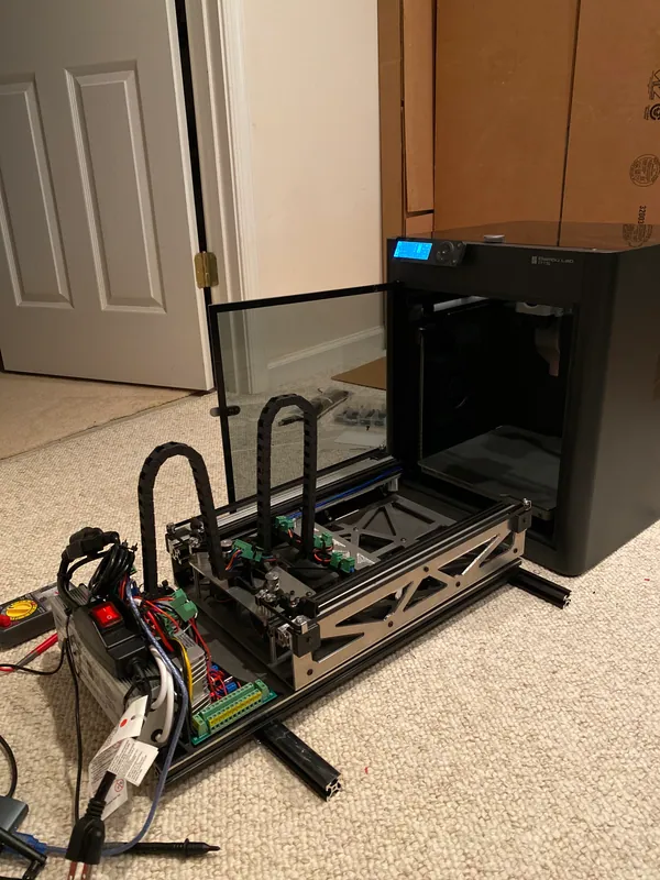
The assembled robot in front of the printer (Jul 29, 2024) Driving into the printer under its own power (Jul 29, 2024) Aug 2024
Custom plates, holders and the full swap
The steel plates, the tape, a third driver so each extension motor has its own, printed braces that tie the printer to the robot, and the two plate holders. The holders were too big for the print bed, so I split each one into printed pieces (five for the right-hand one) and bolted them together. In late August it ran the full swap.
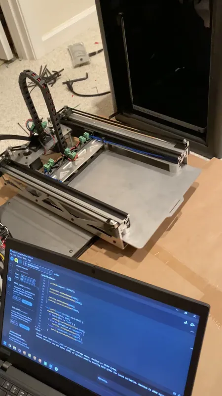
A custom plate held by the magnets after coming out of the printer, the firmware open on the laptop (August 2024) Seating a custom plate in a printed holder (Aug 21, 2024) 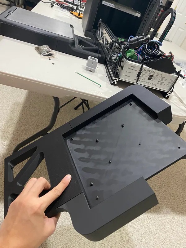
One of the printed plate holders


Results
The full cycle runs autonomously, and it successfully changes the build plate. My FTC team’s usable print time went from about 7 hours a day to 24. Replac3d finished in the top 12 of 2,042 projects worldwide in Hack Club Arcade (summer 2024), winning over $700 in prizes, and won a $300 Polymaker sponsorship.

What I would change
Next time A gripper, not magnets
Make it gripper based. Electromagnets are not a reliable way to hold a build plate.
Next time Simpler and lighter
Make it far less mechanically complex and overbuilt. The FEA below shows that the slides, not the plates, set the limit: about 40 N (9 lb) at full reach, while the machined side plates and magnet plate would only reach theirs at 300 and 960 N. Most of that metal is strength the slides can never use, and most of the parts did not need to be CNC machined.

Calculation How much can the arm hold at full reach?
| Reach | 355 mm, both slides at full stroke | measured from the CAD |
|---|---|---|
| Load | straight down at the build plate’s center, shared by the four magnets, plus the arm’s own weight | magnet positions from the CAD |
| Slides | MISUMI SAR340: clear-anodized aluminum alloy rails, rated 49 N for a pair, fully extended (460 mm), load at the middle of the inner rails | MISUMI catalog |
| Slide rails and 2020 extrusions | aluminum, taken as 6063-T5: minimum yield 97 MPa | 6063 aluminium |
| Magnet and side plates | aluminum, taken as 6061-T6: minimum yield 240 MPa | 6061 aluminium |
| Bottom plate | 3 mm laser-cut steel (1008 sheet at this thickness, no set minimum yield), taken at the low end of mild steel’s published range: 172 MPa (25 ksi) | Fabworks, SendCutSend |
| Carriage riding on the slides | about 0.93 kg, 9 N: magnet plate 212 g and extrusions 370 g (CAD volume × 2.70 g/cm³), four 84 g magnets | the CAD, Adafruit 3874 |
- FEA of my CAD: the magnet plate, both carriage extrusions, all three members of each slide, the side plates and the bottom plate, in 10-node tetrahedra, solved in CalculiX. Bolted joints are bonded, each ball cage is a row of links along the balls’ lines of contact, and the bottom plate is held at the eight turntable standoffs
- Safety factor 2: each part may reach half its minimum yield: 48.5 MPa for the slides and extrusions, 86 MPa for the steel bottom plate, 120 MPa for the aluminum plates
- Weakest part: each slide’s middle member, in the 36 mm between its two ball cages, where it alone carries the arm’s bending. It reaches 48.5 MPa at 56 N (12.5 lb) at the magnets; refining the slides’ mesh from 6 to 3.6 mm elements changed that by 5%
- Outside the slides, the steel bottom plate is next at about 70 N (refining its mesh from 7.2 to 3 mm changed that by 5%), then the carriage extrusions at 210 N, the side plates at 300 N and the magnet plate at 960 N
- The maker’s rating is lower still: 49 N − 9 N of carriage = 40 N at the magnets. My load sits 236 mm past the ends of the fixed rails, less than the 260 mm of the rated case, so the rating is on the safe side
About 40 N (9 lb) at full reach, set by the slides’ rating; the FEA’s 56 N agrees. My 1.6 kg steel plate is 16 N of that, which leaves about 24 N (2.4 kg) for the print.
FEA estimate from my CAD, not a test. The ball cages sit where they roll to at 355 mm; in a real slide the middle member floats between its stops.
Next time Start over MQTT
Connect it to the printer over MQTT for reliable wireless operation, since the start button sometimes failed to actuate.
Next time A plate magazine
Build a magazine with several build plates, for true self-reloading.