← All projectsFIRST Tech ChallengeApr to Aug 2023
PowerPlay Off-Season Robot
My first CAD-designed robot
An off-season FTC robot with string-driven drawer slides and a belted virtual four bar, and the first robot I ever designed in CAD.
This was the first robot I ever designed in CAD: an off-season robot for my FTC team, S.T.A.T.I.C. (FTC 18996), after the 2022-23 POWERPLAY season. It lifts with two towers of string-driven drawer slides and swings the cone with a belted virtual four bar on top of them.
It went from my first drivetrain CAD in April 2023 to the lift moving beside a junction pole on Aug 29. Most of what I learned came from what went wrong: printed pulley bores that stripped, string that frayed and broke, and planetary gearbox stages with a lot of friction. On later robots I stopped printing bores into pulleys.
POWERPLAY, and a robot in the off-season
In POWERPLAY, the 2022-23 FIRST Tech Challenge game, robots pick up plastic cones and drop them over poles called junctions; the high junctions are the tallest. 2022-23 was my first season as captain of S.T.A.T.I.C., and the first time our team advanced to regionals (that season's robot).
After the season I designed a new robot for the same game, my first project in CAD, in Fusion 360. This page follows it from the first drivetrain screenshots in April 2023 to the lift moving beside a junction pole at the end of August, using my CAD screenshots, photos and test clips.
One cycle, from real test clips
A POWERPLAY cycle goes: grab a cone, lift, swing it out over the pole, drop it, come back. Here one plays out in my test clips from Aug 25 to 29, 2023, put in that order. They are separate tests, and they stop short of dropping a cone on a pole.
Grab, then lift
The claw's curved printed jaws wrap around the body of the cone. In this test the arm is lifted by hand, with a cone in the claw.
Then two towers of drawer slides, pulled up by string, raise the arm. The second clip at the top of the page is the lift rising beside a junction pole on our practice field, on Aug 29.
Swing over, and reach
A servo swings the belted arm from folded back over the chassis, over the top, to out in front: the first clip at the top of the page, driven from a handheld servo tester.
At full reach the cone is held high above the field wall. This check was by hand: flip the arm over and hold it up to see where the cone ends up.
Come back
The arm swings back to fold over the chassis and the lift comes down, ready for the next cone. Here the arm runs on the servo tester, from out in front to folded back.
Learning CAD on the drivetrain
The first CAD in my photos is the drivetrain. In April 2023 there is a drive module between two plates with its motors, and a dead-wheel odometry pod: a small unpowered wheel on a pivot, hanging from the side plate between the drive wheels, that measures how far the robot has moved over the floor.


By May the chassis was a box of aluminum channel on mecanum wheels, with a custom side plate over the wheels on each side. Those side plates went through several pocket layouts: a sketch of pockets drawn over a solid plate on Apr 30, the plain plate on May 4, a triangulated pattern on May 12, and a new layout drawn over the plate in red on Jun 1.

The side plate, layout by layout
Apr 30, 2023
A sketch over the solid plate
The first pocket pattern, sketched in white straight over the side plate, with the wheels and the odometry pod behind it.
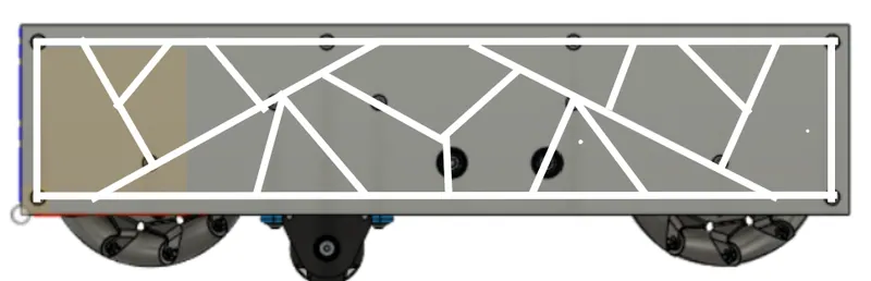
Apr 30, 2023: the first pocket sketch over the side plate May 4, 2023
The plain plate
The side plate with no pockets at all, with the wheels and the odometry pod behind it.
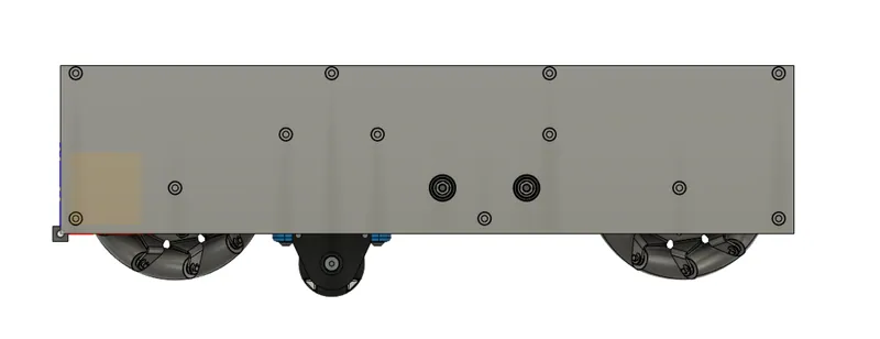
May 4, 2023: the plain side plate, with the wheels and the pod May 12, 2023
Triangulated pockets
A layout of triangulated pockets between thin webs, cut through the whole plate.
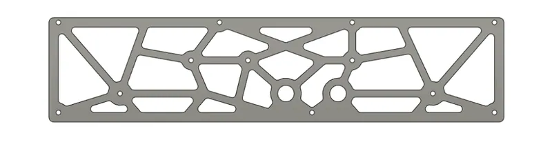
May 12, 2023: a triangulated pocket layout Jun 1, 2023
The next layout, in red
A new layout drawn by hand in red over the plate.
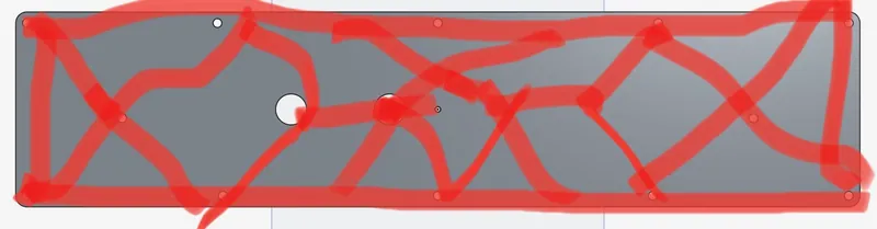
Jun 1, 2023: the next layout, drawn over the plate in red Jul 29, 2023
Built
The finished plate on the robot, with the mecanum wheels and gears showing through the pockets. The drivetrain was built by early August and driving on our practice field by Aug 15, before the lift went on.
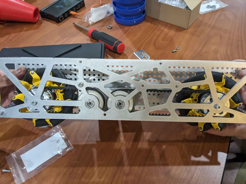
Jul 29, 2023: a finished pocketed side plate over the mecanum wheels


The lift: string-driven drawer slides
Slides show up in the CAD in May: an early render on May 22 has long slide stacks drawn out, two up and two forward.

The lift is two towers, one on each side of the robot. Each tower is a stack of three drawer slides with printed caps on top.

A printed spool on a motor at the base winds in string. The string runs up the stages and turns over printed pulleys at their tops, so winding it in pulls the stages up. The spool in the photo sits on a gearbox built from stacked planetary stages.

On Aug 29 the lift was being strung. Pulled up by hand, the stages rise with the string running up beside them and over a printed pulley block at the top of each stage, until the tower stands at full height.
What went wrong in the lift
Problem Printed bores stripped
I printed the bores straight into the pulleys, and they stripped out completely on the 5 mm shafts.
Fixed on later robots Aluminum hubs
Aluminum hubs bolted into the printed pulleys. I carried that forward: on my 2023-24 robot the printed spools are built around aluminum hubs, so the shaft drives metal instead of plastic.
Problem String, stringing and tension
My stringing was poor, our tensioning was poor, and the string we used frayed and broke.
Changed on later robots Belt instead of string
Belt. In my later FTC seasons I used belt instead of string.
Problem Friction in the planetary gearboxes
I used REV planetary gearboxes, and they had a lot of friction. They are individual stages that you assemble into a gearbox yourself, and assembling REV stages that way is easy to get wrong.
Next time
Go with goBILDA gearboxes, which do not come as individual stages you assemble.

The arm: a belted virtual four bar
On top of the lift sits the arm that carries the cone out over the pole. It is a belted virtual four bar. A parallel four bar uses two equal links so the end keeps its angle as the arm swings; a virtual four bar gets the same effect from one arm and a belt, which runs along the arm from a pulley at the pivot to a pulley at the claw end.
The arm swings from folded back over the chassis, over the top, to out in front. Its pivot is driven by a servo through a gear reduction: a small pinion on the servo turns a large aluminum gear on the pivot shaft. Threaded rods tie the tops of the two towers together.

The claw
The claw closes curved printed jaws around the body of the cone, driven by a servo through a gear stage. By Aug 17 it was in CAD, drawn around a cone; by Aug 25 the parts were printed and it held a cone on the robot.


The whole robot
By Aug 21 the whole robot was in CAD: two lift towers on the pocketed drivetrain, with the arm drive on top. Five days later it stood on our practice field with its lift and arm up, and on Aug 29 the lift went down and back up beside a junction pole.


What I would do differently
Next time
Bolt aluminum hubs into every printed pulley and spool instead of printing the bore.
Next time
Use belt instead of string for the lift.
Next time
Use goBILDA gearboxes instead of REV planetary stages assembled by hand.
What carried forward
This robot is where I learned CAD, and its failures set habits I kept. The printed spools on my 2023-24 robot are built around aluminum hubs, and in later seasons I used belt instead of string.
