← All projectsS.T.A.T.I.C., FTC 18996Sep 2023 to Feb 2024

FTC CENTERSTAGE Robot

Our first season with CAD. I was overly ambitious with the design, and the robot came together over the season: 0-5 at our first two events, 3-2 at the last two.

373% OPR increaseFrom the Garrett County Qualifier (Jan 13) to the Chesapeake Championship (Feb 3, 2024)
6 awardsJudged awards in 4 events, including Inspire 2nd Place
The finished robot running its autonomous on our home field: it leaves one pixel by the red team prop, drives to the backdrop and swings its arm up to place the other
Jan 19, 2024: the flaps pull a white and a purple pixel in off the floor, and the arm lifts both out of the robot together

CENTERSTAGE was the 2023-24 FIRST Tech Challenge game, and this is the robot my team, S.T.A.T.I.C. (FTC 18996), built for it. It was our first season with CAD, and I was overly ambitious with the design: a flap intake, two cradles with color sensors, an arm that swings back into the robot to grab both pixels at once, a two-motor lift, a deposit that shifts sideways to line up with the backdrop, a drone launcher and hooks for hanging.

The robot came together over the season. We lost every qualification match at our first two events, then went 3-2 at both of the last two, won the Inspire Award 2nd Place at the Laurel 2 Qualifier, and ranked 7th of 27 in our division at the Chesapeake Championship.

The autonomous, from the code

Each match opens with an autonomous period, when the robot drives itself. Ours finds the team prop with the camera, leaves the purple pixel on the matching spike mark and places the yellow one on the backdrop. This is our red close routine with the prop on the left, drawn from the Road Runner poses in our code (inches, heading in degrees).

  1. Find the prop

    While the robot waits for the start, the camera thresholds each frame in HSV for red, finds the largest blob and votes by where its center falls: left of 100 px, left of 437.5 px, or further right. It decides after 15 votes; here, LEFT.

  2. Purple pixel on the spike

    From the start pose (12, -61), facing into the field, the robot drives to (15, -41) and turns 30 degrees toward the left spike mark on one line, and the arm leaves the purple pixel there.

  3. To the backdrop

    One more line takes it to (42, -36), turning back to 0 degrees to square up to the backdrop. With the prop on the right it first detours through (36, -57).

  4. Line up on the tag

    The camera reads the center AprilTag, and the code splines to a pose 5.5 in short of it along the measured range, shifted 8.5 in to the left for a left prop (6.5 in to the right for a right one), then pauses 0.25 s.

  5. Yellow pixel

    The lift goes to its first height, 100 ticks, the arm tips to its drop angle and both grabbers open: the yellow pixel lands on the left side of the backdrop.

  6. Back for more

    The four official autonomous programs in the code stop there, with two pixels. An experimental routine goes on: reversed splines under the truss through (27, -6) and (-40, -6) to the stacks at (-62, -17), with the intake on and its front bar at the third stack height, then back to the backdrop.

Robot poses, headings, offsets and thresholds are from our code; the robot is an 18 in footprint. Field elements are placed approximately, splines are drawn through the code's waypoints, and the tag step assumes the camera sees the center tag straight ahead, since the real pose comes from what it measures.

The game, and the robot

In CENTERSTAGE, robots pick up hexagonal game pieces called pixels, from the floor or from stacks, carry them under the truss and place them on the backdrop, a slanted board of staggered rows. Three touching colored pixels, all one color or all different, score extra as a mosaic. Each match starts with an autonomous period and ends with launching a paper airplane drone and hanging from the rigging.

2023-24 was our first season with CAD, and we drew the whole robot in Fusion 360. This page follows two pixels through it, then goes through each mechanism, the code, and how the season went. I do not have the CAD file of this robot at the moment, so everything here is built from our photos, clips, renders and code.

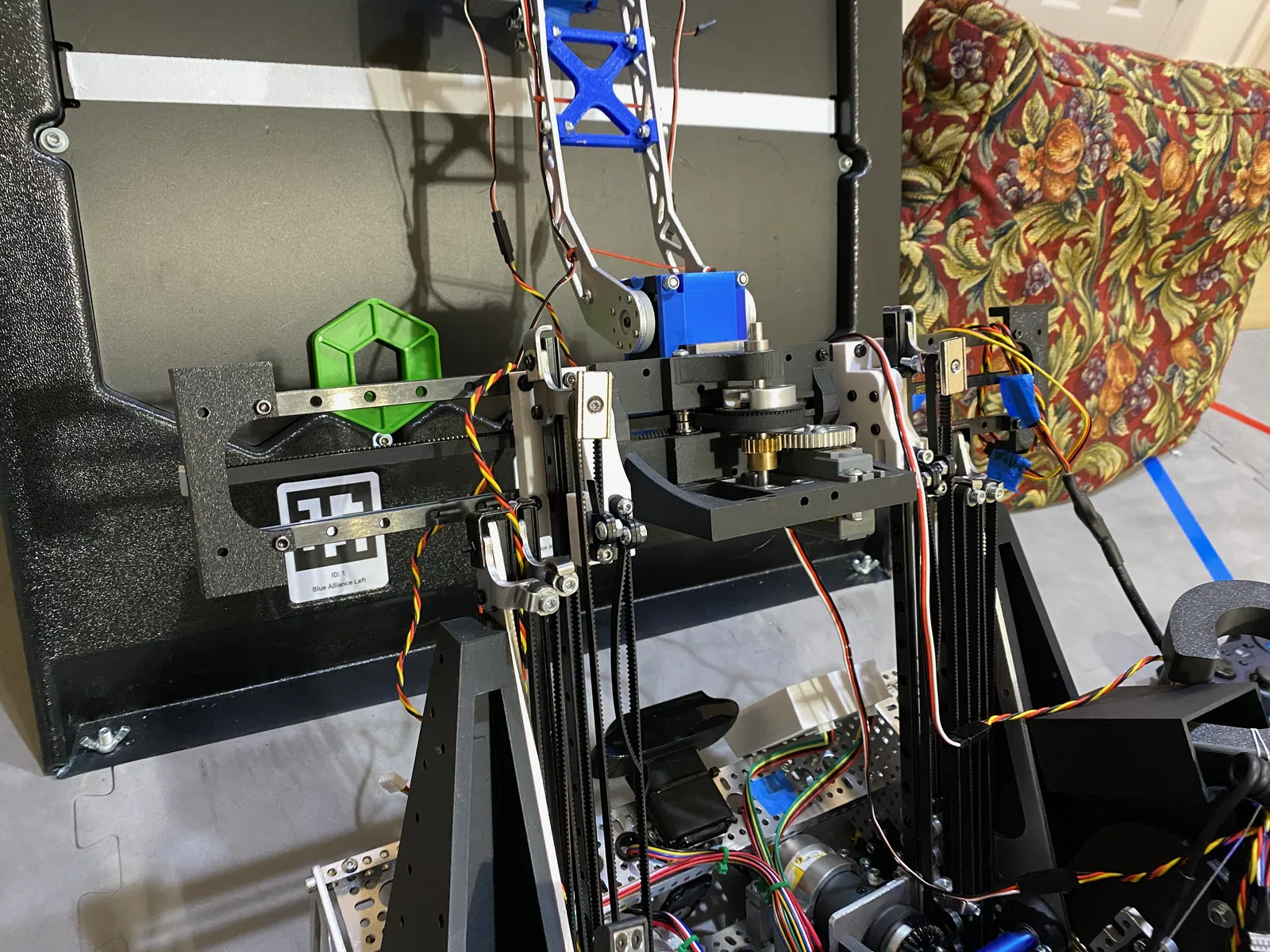
Feb 17, 2024: the finished robot at a backdrop, lift and arm up, the flap intake at the front

One cycle, start to finish

The robot scores with one loop, and each stage of it is a few lines of our code. The clips beside the text are the real robot; the numbers in brackets are servo positions from the code, on the 0 to 1 scale a servo is commanded on.

1. Intake. A roller of rubber tubing flaps at the front pulls pixels in off the floor. The driver runs it on the right trigger, and two servos set the height of the front bar: one position for the floor (0.008) and four more, 0.015 to 0.042, for taking pixels off the top of a stack. While the intake runs, the code turns the drive controls around, so the intake side is the front for the driver.

Jan 19, 2024: intake and cradles. Pixels go in, and the Driver Station reads "Slot One: Green, Slot Two: Purple"

2. Cradles and color sensors. The two pixels land side by side in two printed cradles shaped like the pixel, each with a color sensor under it (how it reads the colors). As soon as both cradles read a pixel, both controllers rumble for 0.3 s, the roller runs backward for 0.6 s, and the Driver Station shows both colors.

3. Transfer. The code opens both grabbers and the intake cover, drives the lift down to its limit switch and parks the arm (0.24), then swings the arm back into the robot onto the pixels (0.11). Both grabbers close, open for 60 ms and close again, and the arm lifts out with both pixels at once.

Jan 19, 2024: the transfer. The arm comes down, grips, and lifts out with both pixels

4. Lift and arm. The arm swings up and out toward the backdrop (0.71), and the wrist servo turns the grabbers to the placing angle (0.37). Two motors run the lift up its two slide packs; our final teleop steps it through ten heights on the D-pad, from 100 to 1,900 encoder ticks.

5. Place. Each grabber opens on its own (open 0.75, closed 0.25), one on each bumper of the second controller, so the two pixels can go to two different spots. In autonomous the arm tips to its drop angle (0.73) and both open. Then one button sends everything back for the next two: lift down to its limit switch, deposit to the center of its rail, arm folded, cover closed.

Lift, arm and place, at the end of the autonomous run at the top of the page: the arm swings up to the backdrop

Designing it: our first season in CAD

We drew the whole robot in Fusion 360, and its parts came out of it three ways: 3D printed, laser cut in aluminum by Fabworks, and, from late December, machined on a benchtop CNC router.

Dec 8, 2023: the whole robot in Fusion 360: lattice-cut sheet chassis, two angled slide packs, the first intake at the front

The arm link

The arm link is a good example. It started as a sketch in Fusion with the cutouts drawn in, and was laser cut in 6061-T6 aluminum by Fabworks with a pattern of triangular truss cutouts.

Nov 28, 2023: the bent arm link sketched in Fusion, cutouts drawn in
The arm link as cut, with triangular truss cutouts

Fabworks cut our sheet parts. A box on Nov 18 held a lattice-cut plate like the chassis sides, and a later order lists the arm link, the intake arms, a lift mount and an intake motor side plate in the same aluminum, plus mounts for MGN rail blocks in 1008 steel, all laser cut with hole operations.

Nov 18, 2023: laser-cut parts from Fabworks: a perforated plate, a lattice-cut side plate and small brackets
Our Fabworks order: the curved arm link in 6061-T6 aluminum and MGN rail block mounts in 1008 steel

Problem Printed bores strip

On my POWERPLAY off-season robot earlier in 2023, my first project in CAD, I printed the bores straight into the pulleys, and they stripped out completely on the 5 mm hex shafts.

Fix Aluminum hubs inside printed pulleys

Aluminum hubs bolted into the 3D-printed pulleys. I carried that lesson forward: on this robot the printed pulleys and spools are built around aluminum hubs, so the hex shaft drives metal instead of plastic.

Printed parts still had their limits. On Jan 12, the night before our second qualifier, a printed pulley cracked through beside its aluminum hub.

Nov 17, 2023: a printed spool built around a bolted-in aluminum hub
Jan 12, 2024: a printed pulley cracked beside its aluminum hub

From late December we also machined aluminum on a benchtop CNC router. On Dec 29 it engraved and drilled a plate with our STATIC logo, held down with green printed clamps.

Dec 29, 2023: the router engraving and drilling an aluminum plate held in green printed clamps
The finished plate, STATIC engraved

Chassis and drive

The chassis is two laser-cut aluminum side plates with lattice cutouts, with the mecanum wheels running inside them and the control hubs standing on edge on printed towers. The drive constants in our code are for 435 RPM motors.

For position the code uses three unpowered tracking wheels instead of the drive wheels: two parallel wheels 12.59 in apart and one sideways wheel 6 in ahead of center, each on an 8,192-count encoder.

Calculation How fine is one tick of a tracking wheel?

Tracking wheel radius0.73 inour code
Counts per turn of the encoder8,192REV Through Bore Encoder
Distance between the two parallel wheels12.59 inour code
  1. One turn of a wheel: 2π × 0.73 in = 4.59 in of travel
  2. One tick: 4.59 in / 8,192 = 0.00056 in (0.014 mm)
  3. Heading: one tick of difference between the two parallel wheels is 0.00056 in / 12.59 in = 0.000044 rad = 0.0026 degrees

One tick is about half a thousandth of an inch of travel and about 0.003 degrees of heading.

From the constants in our code, before its tuned X and Y multipliers (about 0.955); rounded.

We tuned the drive's feedforward on FTC Dashboard in mid January by comparing target and measured velocity. The final values in the code are kV 0.01375, kA 0.00427 and kStatic 0.01675, with paths limited to 45 in/s.

Jan 4, 2024: the side plate, lattice-cut aluminum with the mecanum wheels inside and a control hub on its printed tower

Calculation How fast does the first move of the autonomous get?

kV and kStatic, tuned0.01375 per in/s, 0.01675our code
Path speed and acceleration limits45 in/s, 25 in/s²our code
Start pose to the left spike mark (red, close)(12, -61) to (15, -41), inour code
  1. Full power, from the tuned feedforward: v = (1 - 0.01675) / 0.01375 = 71.5 in/s, so the 45 in/s limit is 63 % of it
  2. Reaching 45 in/s at 25 in/s² takes 45 / 25 = 1.8 s and 45² / (2 × 25) = 40.5 in; with the same distance to slow down, a move has to be over 81 in long to touch the limit
  3. The first move: √(3² + 20²) = 20.2 in, so it peaks at v = √(25 × 20.2) = 22.5 in/s
  4. Its time: 2 × 22.5 / 25 = 1.8 s

The spike mark move peaks at about 22.5 in/s, half the path limit, and takes about 1.8 s: on moves this short the acceleration limit, not the speed limit, sets the time.

Estimate: a straight line on a trapezoidal speed profile, leaving out the 30 degree turn made on the same move; the feedforward line ignores kA and battery voltage.

Jan 18, 2024: target and measured drive velocity on FTC Dashboard while tuning

The intake: two versions

  1. Version 1 · Dec 2023

    Star wheels and a roller drum

    The first intake used star wheels and a drum of compliant rollers feeding a printed ramp into a two-pocket tray under a curved cover. It was still being put together on Dec 15, the day before our first event, and we replaced it after that event.

    Dec 15, 2023: the first intake, star wheels on a belt drive
    Dec 15, 2023: the first intake, star wheels on a belt drive
    The first intake: star wheels, the roller drum, and the two-pocket tray under the cover
  2. Version 2 in CAD · Dec 26, 2023

    Rubber tubing flaps

    Ten days after the first event the second intake was in CAD: rows of rubber tubing flaps held on aluminum tubes, driven by a belt from the side, with a printed cradle for the pixels behind the roller.

    Dec 26, 2023: the flap intake in Fusion 360
    Dec 26, 2023: the flap intake in Fusion 360
    Our render of the flap intake, pulled apart: side plate, flap roller, belt and pulleys, and the pixel cradle
  3. Version 2 built · Jan 2, 2024

    Floor and stack

    By Jan 2 it was built and running. The flaps pull pixels in off the floor, and with the front bar raised they knock the top pixels off a stack of five one at a time. This is the intake we ran for the rest of the season.

    Jan 2, 2024: the built intake, rubber tubing flaps on gold aluminum tubes, held with zip ties
    Jan 2, 2024: the built intake, rubber tubing flaps on gold aluminum tubes, held with zip ties
    Jan 2, 2024: the flaps take the top pixels off a stack of five, one at a time

Cradles and color sensing

Behind the roller the two pixels land in two printed cradles shaped like the pixel, under a shaft of foam wheels. A color sensor under each cradle tells the code what is there, sorted by which of its red, green and blue readings is strongest.

Jan 11, 2024: two pixels in the cradles, cover lifted
From IntakeSubsystem.identifyColor in our code.
ReadingReads as
Red, green and blue all under 200Empty
Blue, then green, then redPurple
Green, then red, then blueYellow
Green, then blue, then redGreen, or white when blue is over 2,500 (slot 1) or 2,000 (slot 2)

The colors go to the Driver Station, and the drivers need them: a mosaic takes three colored pixels that are all one color or all different.

Jan 12, 2024: the foam wheels above the two cradles

The transfer

For the transfer the lift drives down to its limit switch, the arm swings back into the robot over the cradles, and two grabbers close on the two pixels. A wrist servo turns the grabbers between the pick-up angle and the placing angle, and each grabber opens on its own.

Problem The arm left with one pixel of two

Through mid January the arm came down, gripped both cradles and lifted out with only one pixel. We have it on video on Jan 13, the morning of our second qualifier, and again on Jan 17 and Jan 18.

Result Both pixels by Jan 19

By Jan 19 the arm lifted both pixels out in all five clips we recorded that day, like the transfer clip above.

Jan 13, 2024: the arm grips both cradles and leaves with only the purple pixel

The lift

Two motors drive two angled slide packs. The code holds the lift at a target height with a proportional term plus a constant push in the direction of the error, limits how hard it can drive down to half power, and re-zeroes on a limit switch at the bottom every time the robot goes back for pixels.

power = 0.005 × error
      + 0.07 × sign(error)
limited to -0.5 ... 1

Both motors get the same power, worked out from one motor's encoder. In the touchpad teleop each row of the backdrop is 200 ticks above the one below.

One slide pack pulled to full extension by hand

A sideways axis for the backdrop

The backdrop's rows are staggered by half a pixel, so the spot under the deposit shifts from row to row. Instead of moving the whole robot, the arm's pivot rides a carriage on two short rails across the top of the lift, and a servo shifts the arm and the deposit sideways.

Jan 13, 2024: the top of the lift. The arm's servo and pivot ride a carriage on two short sideways rails, with a belt between them

In the code the rail has a center position and stops 0.067 of servo travel apart: five stops for one kind of row, and six, offset by half a stop, for the other. The rail was first driven by a DC motor with an encoder and was changed to a servo; the code still carries the motor version, commented out.

Every servo on the deposit rides up and down with the lift, so their wiring runs through a breakout board and a coiled cable that stretches as the lift extends.

Jan 27, 2024: fitting the breakout board and coiled cable that carry the deposit's servo wiring up the lift

Two pixels, two rows

A schematic of the backdrop and the deposit, with the lift targets and servo values from our touchpad teleop.

  1. Two pixels, two places

    The deposit carries two pixels side by side, one in each grabber. Say the yellow one goes in row 3 and the purple one in row 4, half a pixel further right. In our touchpad teleop the second driver picks both spots on the PS4 controller's touchpad and presses one button.

  2. Up to row 3

    The arm swings up (0.71) and the lift runs to row 3's target, 500 encoder ticks; each row is 200 ticks above the one below. On this row the pair lines up with one of the five whole-pixel stops, so the rail stays on the center stop, C, at 0.740.

  3. Left grabber opens

    The arm tips to its drop angle (0.73), the left grabber opens (0.75), and the yellow pixel stays on the backdrop. The arm comes back up and the left grabber closes again.

  4. Half a pixel over

    The lift climbs to row 4, 700 ticks. This row is offset by half a pixel, so the rail moves to upper stop D at 0.7065, half a stop from where it was. The right grabber opens and the purple pixel lands.

  5. Back to stasis

    One more command sends the lift down to its limit switch, the rail back to center stop C and the arm back into the robot.

    Our final teleop did this by hand instead: the D-pad steps the lift through ten heights and the rail in half-stop steps, and the bumpers release each pixel.

Schematic, not to scale: hexagons are pixels, the blue bar is the deposit with its two grabbers, and the line under it is the sideways rail with its stops, drawn in the code's order with A on the left. One stop of rail travel is drawn as one pixel width. Lift targets, servo values and the order of moves are from our touchpad teleop.

Drone launcher and hang

The drone launcher is a motor with two wheels that flings the paper airplane; one button spins it for 2 s. It was printed as one piece together with a servo mount, and the first print did not line up: a screw hit the launcher and the holes were off.

For the hang, printed C-shaped hooks sit on top of both slide packs. The lift runs up to its hang height, 1,800 ticks, the hooks go over the rigging, and the lift pulls the robot up.

Problem The hang only held while powered

On Jan 11 the robot hung from our practice rigging, then dropped as soon as the motors were unpowered.

Jan 11, 2024: the robot hangs on its hooks from our practice rigging, then drops

The code

Our robot code is public: STATIC-CENTERSTAGE on GitHub. It is Java on FTCLib's command-based framework, with Road Runner for the autonomous paths.

  • Structure. Each mechanism is a subsystem (intake, deposit, lift, and one for the drone and hang), and each driver button schedules a short sequence of commands, so a whole transfer, or a whole return to stasis, is one button press.
  • Autonomous. Before the start the camera looks for our team prop and votes left, middle or right. The robot pushes the purple pixel onto the matching spike mark, drives to the backdrop on a Road Runner path, and uses the center AprilTag on the backdrop to correct its final position before placing the yellow pixel. It is drawn at the top of this page.
  • Touchpad placement. One teleop lets the second driver pick a row and column for each pixel on the PS4 touchpad, shows the choice on a small LED display on the robot, and runs the lift, arm and sideways rail to both spots with one button.
  • Driver feel. Our final teleop scales each stick to 87/95 of its input and adds a constant 0.08 in the direction it is pushed, the same idea as the lift's constant push. While intaking it turns the controls around, so the intake is the front.
The touchpad subsystem as it appeared in our engineering portfolio
Jan 27, 2024, from above: the robot turns toward the red team prop and the arm reaches out to leave a pixel on its spike mark, then it heads for the backdrop
An autonomous run under the truss to the pixel stacks at the far wall

How the season went

Problem Not ready for the first event

Two days before our first qualifier the lift had just been mounted, and the first intake was still being put together the day before. At the Mount St Joseph Qualifier on Dec 16 we lost all five qualification matches and ranked 21st of 21.

Fix Rebuild between events

In the four weeks after, the deposit reached the top of the backdrop and the flap intake replaced the first one. The second qualifier on Jan 13 still went 0-5, with the transfer grabbing only one pixel of two. With both pixels transferring and a week of drive and autonomous tuning, we went 3-2 at the Laurel 2 Qualifier on Jan 28, ranked 9th of 25, and were picked by the first-seeded alliance.

Dec 12, 2023, four days before the first qualifier: the chassis wired on the floor
Dec 16, 2023: in the pits at the Mount St Joseph Qualifier

At the Chesapeake FTC Championship on Feb 3 we went 3-2 again and ranked 7th of 27 in the Stage Right Division. In our first match our alliance scored 100 points in autonomous and won 208-151, our best score of the season. As part of the fourth-seeded alliance we reached the semifinal and lost it 1-2.

Chesapeake Championship, Qualification 7: 208-151, with 100 points in autonomous
Laurel 2 Qualifier, Qualification 15: our alliance wins 186-45
Laurel 2 Qualifier: Inspire Award, 2nd Place

Official results

  • Mount St Joseph Qualifier, Dec 16, 2023: rank 21 of 21, 0-5 in qualification matches, did not advance. Motivate Award 3rd Place.
  • Garrett County Qualifier, Jan 13, 2024: rank 25 of 25, 0-5, did not advance. Innovate Award sponsored by RTX 3rd Place, and the Judges' Choice Award.
  • APL Laurel 2 Qualifier, Jan 28, 2024: rank 9 of 25, 3-2. Picked by the first seed; lost the semifinal 0-2 (120 to 148, 142 to 148). Inspire Award 2nd Place, Think Award 2nd Place and Control Award 2nd Place.
  • Chesapeake FTC Championship, Stage Right Division, Feb 3, 2024: rank 7 of 27, 3-2. On the fourth-seeded alliance; lost the semifinal 1-2 (211 to 229, 225 to 138, 207 to 243).

Team 18996, 2023 season. Season record 7-18-0: 6-14-0 in qualification matches and 1-4 in playoffs. Source: FIRST Tech Challenge event results.