← All projectsConceptNov 2024
Upcycled CNC Router
A benchtop CNC router gantry designed to be built from the aluminum extrusion of the CENTERSTAGE FTC game field.

A benchtop CNC router I designed to be made out of the aluminum extrusions from the trusses of the CENTERSTAGE FTC game field, meant for cutting aluminum, but also MDF and Delrin. The whole gantry rides front to back on two profile rails, pushed by two ball screws with a stepper motor each, and the carriage runs side to side along the gantry on two more rails and a third ball screw.
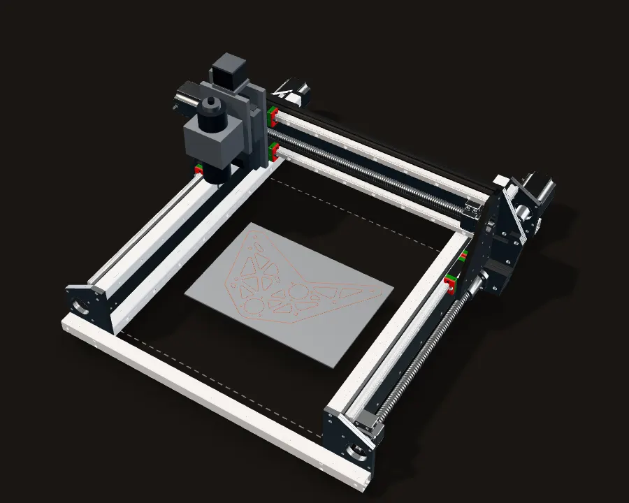
I did not build it. What exists is the X and Y gantry in CAD. On this page it moves about its real axes as you scroll, with a simple Z axis and spindle added (they are not in my CAD), milling an example part: the shorter side plate of my electric bike.
The machine, milling a real part
The CAD runs a toolpath for the shorter of the two aluminum side plates of my electric bike, at its real size, with every line and arc of its outline and holes taken from the e-bike CAD. The gantry, the carriage and all three ball screws move about their real axes as you scroll. The Z axis and spindle are a simple stand-in: my CAD stops at X and Y.
Three axes
The whole gantry, the bridge across the machine, moves front to back: Y. The carriage on it moves side to side: X. Each is a ball screw turned by a stepper motor.
The dashed box is the X and Y travel in the CAD, about 417 x 460 mm. The e-bike plate, 287 x 187 mm, is drawn on a sheet in the middle of it.
Y: two screws, two motors
The gantry moves forward on its own first, out to the row of the first hole. Each side has its own ball screw and NEMA 23, turning together, so the gantry is pushed at both ends while its four carriage blocks slide along the two 600 mm rails.
X: one screw, riding on the gantry
Then the carriage moves on its own, over to the first hole. The X screw, its motor, its BK12 support and its two 550 mm rails all ride on the gantry, so the whole X axis travels with every Y move.
Z: down to the stock
The spindle comes down 73 mm to 5 mm over the stock, spinning, and plunges through the 3.175 mm plate. The first hole is 3.3 mm, only about 0.15 mm wider than the 1/8 in (3.175 mm) end mill, so a single plunge cuts it.
Round holes first
The 14 round holes go first, nearest next each time. The six 3.3 mm holes are plunges. The six 6.2 mm holes and the two 35.1 mm bores are cut around, with the end mill's centre 1.6 mm inside the edge, so the black kerf falls inside the hole.
Then the pockets
Next the slot and the 15 lattice pockets, nearest first again. Their inside corners are 3 mm radius arcs and the slot is 6.2 mm wide (CAD), so the 3.175 mm end mill reaches into every corner.
The outline last
Then the outside, 804 mm around, with the end mill 1.6 mm outside the edge. Cutting it last keeps the plate held in the sheet while every hole and pocket is cut.
Back home
Z goes up, the machine goes home, and the plate lifts out of the sheet.
One screw turn is 5 mm. A 1.8° stepper takes 200 full steps per turn, so one full step moves an axis 0.025 mm (from the part numbers, before any microstepping).
My CNC CAD, moved about its real screw axes (read from the STEP file), running a toolpath made for this page on the exact outline and holes of the e-bike plate, unscaled. The Z axis, the spindle and the end mill are not in my CAD: they are a simple generic unit (a plate, two rails, a ball screw, a small stepper and a spindle clamp) added so the toolpath reads as milling. The end mill's path runs half its width off the plate's edges, in one pass to full depth; a real job in aluminum would step down in several shallower passes. The stock, the black kerf (the end mill's full width), the dashed blue rapid moves and the travel box are overlays, not parts.

Built from a game field
The frame is six 2 ft lengths of 1 x 1 in aluminum extrusion from the trusses of the CENTERSTAGE game field: two stacked along each side, and one across each end. A 4.8 mm (3/16 in) side plate stands on the outside of each pair, and stacked end plates close off both ends; the pair at the back carries the two Y motors.
The motion hardware is off the shelf and named by part number in the CAD: HIWIN HGH15 profile rails, SFU1605 ball screws on BK12 supports, NEMA 23 stepper motors with bore-reducer couplers, and 550 mm lengths of 2020 extrusion for the X beams. The plates that tie it all together are mine.
Why I designed it, and why it stayed in CAD
Problem Outsourcing every CNC part
I was making a lot of projects that needed CNC-cut parts, and having all of them cut for me adds up.
Fix
Owning a CNC would save a lot compared with outsourcing, so I designed one around extrusion I could get for free: the trusses of the CENTERSTAGE game field. The goal was cutting aluminum, but also MDF and Delrin.
Problem It would not pay for itself in time
Then I realized that what I would put into building it would be more than everything I would spend on CNC-cut parts between finishing it and leaving for college, where I would have access to lots of manufacturing equipment.
Fix
So I did not build it. The design stops at the X and Y gantry in CAD.
What it is built from
The CAD, part by part, turning as you scroll.
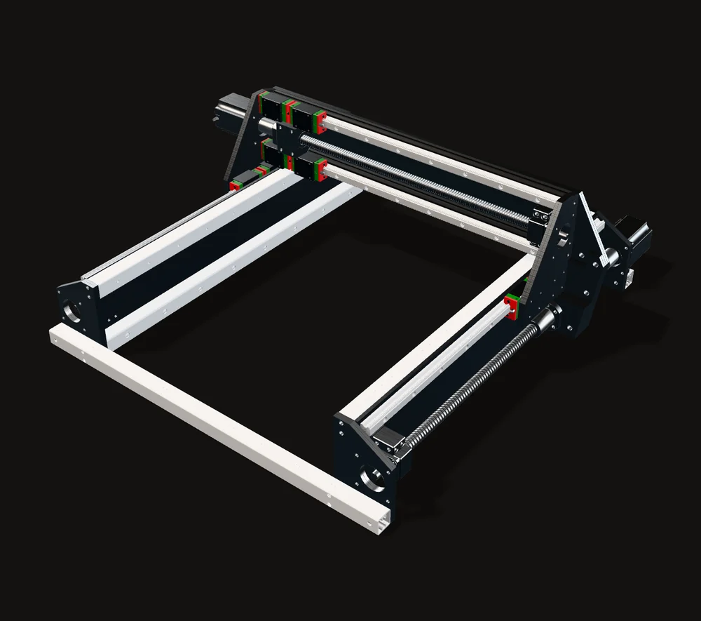
The frame
Six 2 ft lengths of 1 x 1 in extrusion from the trusses of the CENTERSTAGE game field: two stacked along each side, one across each end.
Y: two 600 mm rails
HIWIN HGH15 profile rails, 600 mm long, one on the outside of each side plate. Each rail has two carriage blocks, and the gantry rides on all four.
X: two 550 mm rails
Two more HGH15 rails, 550 mm long, each on a length of 2020 extrusion across the gantry, with two blocks each. The four blocks and the ball nut are the X carriage; the plate that would tie them together and carry a Z axis is not in the CAD yet.
Ball screws
Three SFU1605 ball screws, 16 mm across with a 5 mm lead: two 600 mm screws for Y and a 550 mm screw for X. Each has a BK12 fixed support and a coupler from the motor's 6.35 mm shaft to the screw's 10 mm end.
Dual-drive Y
From the back: each Y screw has its own NEMA 23 (23HS30-2804S, 1.8° per step, 1.9 N·m holding torque). The two turn together, so the gantry is pushed at both ends.
The gantry
The gantry is one 678 x 216 mm plate, 4.8 mm thick, with reinforcement plates front and back at each end. A stack of five spacer plates at each end steps out to the Y ball nut, and end plates carry the two X beams, the X motor on the left and the X screw's BK12 on the right.
Screws and bolts are left out; every other part is my CAD as modelled. Sizes are measured in the CAD.
Five millimetres per turn
The right Y ball screw up close, cut through its own axis. Scroll to turn it.
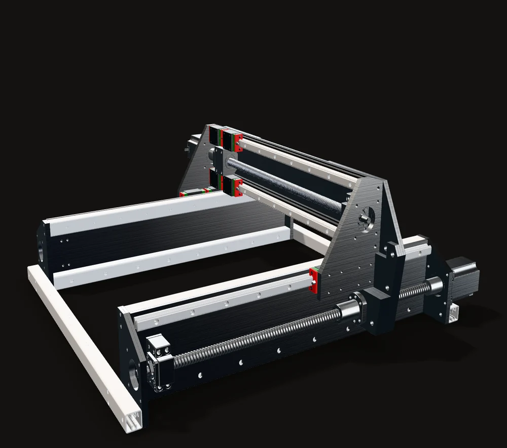
Motor to screw
At the back of the machine the NEMA 23 drives the screw through a bore-reducer coupler: 6.35 mm on the motor side, 10 mm on the screw side, straight through with no belt or gears.
Four turns, 20 mm
The screw is held in place and turns; the ball nut on it cannot, so it moves 5 mm along the screw for every turn. The nut is bolted to the gantry through the stack of five spacer plates, and the whole gantry moves with it while the carriage blocks slide along the rail.
Four turns of the motor, 800 full steps, move the gantry 20 mm.
The fixed end
At the front, the screw's 12 mm journal sits in a BK12 support block, which holds the screw both along and across its axis.
Both sides at once
The cut lifts away. Both Y screws turn together, each on its own motor at the back, and the gantry keeps moving square to the frame.
Cut faces are hatched. The screw turns about its axis as read from the STEP file; the motor spec is StepperOnline's for the part number in the CAD. The push is computed from the holding torque and the lead, with a 90 % efficient screw assumed.
The numbers in the CAD
Everything in this table is read from the CAD, from the part numbers in it, or computed from them.
| X (side to side) | Y (front to back) | |
|---|---|---|
| What moves | The carriage: four blocks and the ball nut | The whole gantry, with the X axis on it |
| Rails | Two HGH15, 550 mm, on 2020 extrusion | Two HGH15, 600 mm, on the side plates |
| Ball screws | One SFU1605, 550 mm | Two SFU1605, 600 mm, one per side |
| Motors | One NEMA 23 | Two NEMA 23, turning together |
| Travel in the CAD | About 417 mm | About 460 mm |
| Per screw turn | 5 mm | 5 mm |
| Per full motor step | 0.025 mm | 0.025 mm |
Why ball screws and profile rails
I chose ball screws and profile rails for their stiffness and rigidity; they are the industry standard for CNC machines. A ball screw also turns a motor's torque into a large push along the axis.
Calculation How hard can one Y screw push the gantry?
| Motor holding torque | 1.9 N·m | 23HS30-2804S datasheet |
|---|---|---|
| Ball screw lead | 5 mm per turn | SFU1605, the part number in the CAD |
| Ball screw efficiency | about 90 % | Machine Design: "usually above 90%" |
- One turn moves the nut 5 mm, so F × 0.005 m = 2π × T × η
- F = 2π × 1.9 N·m × 0.9 / 0.005 m ≈ 2,150 N per screw
- Two Y screws, turning together: about 4,300 N on the gantry
- Resolution: 5 mm / 200 full steps = 0.025 mm per step
At holding torque one Y screw can push with about 2.1 kN, and the pair about 4.3 kN, with 0.025 mm per full step.
Upper bound, static: a stepper's torque falls as it speeds up, and drivers rarely run it at its full holding torque. Rounded.
Travel, lead and step size set the geometry of the machine. How fast and how hard it could really cut would depend on the spindle, the motor drivers and a real Z axis, and none of those are in my CAD.
