← All projectsPersonal projectJun to Aug 2025
Electric Bike
5.3 kW mid-drive conversion
A standard bicycle converted into a 5.3 kW mid-drive e-bike, with every custom part designed by me.
I converted a 2019 Trek Dual Sport 2 into a 5.3 kW mid-drive e-bike and designed its powertrain. Two 2.6 kW brushless motors share one serpentine belt, two jackshaft axles carry the drive through a second belt, and a 20-tooth sprocket drives the bike's own chain with 100 N·m of torque.
It reaches about 35 mph, with about 20 miles of range on a 48 V, 16 Ah pack and a VESC controller. The CAD took about two days, and I did the build on my own, with carbon fiber plates cut by an outside shop, bent and powder-coated 5052 aluminum, a stainless adapter plate, and parts I 3D printed.
How the drivetrain works
Five section views of my CAD, from the motors to the chain. The drive turns as you scroll, every part at the speed its tooth count gives it.
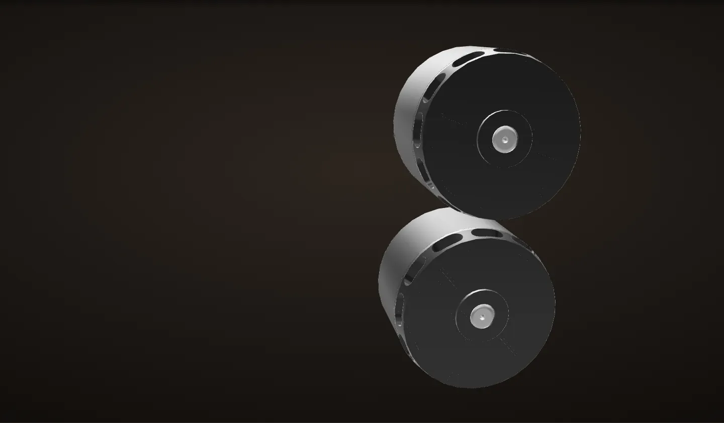
1. Two low-KV motors
Two SKP 6465 brushless outrunners, 2.6 kW each and 5.3 kW together. At 150 KV on a 48 V pack their nominal no-load speed is about 7,200 rpm (150 x 48), and the two belt stages bring that down to about 444 rpm at the chain sprocket.
The cut goes straight across both motors through the middle of the stator. The 12-tooth stator stays still, and the rotor, a ring of 14 magnets, spins around it and turns the shaft. Each shaft carries a 16-tooth HTD 5M belt pulley on the other side of the motor mount.
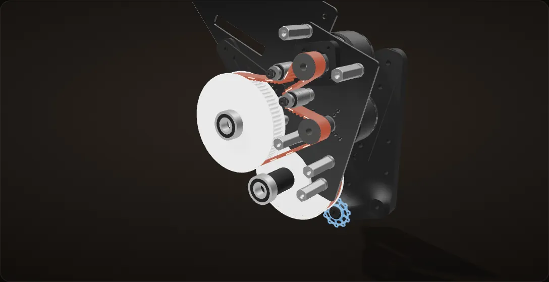
2. The first belt: a serpentine
Stage one is 4.5 : 1. Both 16T motor pulleys sit on one 115-tooth HTD 5M belt (575 mm) that drives a 72T pulley.
Two backside idlers, each a stack of four 626 bearings, bend the belt into an S between the motors, so it wraps motor 1's pulley 135 degrees and motor 2's 207 degrees. A plain triangle around the same three pulleys would wrap them only 68 and 99 degrees: 3 and 4 teeth in mesh instead of 6 and 9.
Both motors ride the same belt, so they always turn at exactly the same speed.
3. The jackshaft axles: making standards work together
The drive runs on two 14 mm keyed axles. Axle 1 carries the 72T pulley and a 20T pulley. Axle 2 carries the second 72T pulley, a 14 mm keyed robotics hub, and a stainless steel adapter plate that couples the hub to a bicycle chain sprocket (1/2 x 3/32 in), with a 1/4 in spacer between them.
Everything is built around that one shaft size: HTD pulleys with 14 mm keyways, 6202 bearings with 14 mm bores and the keyed hub. 3D-printed spacers of 1.6, 2.2, 24.6 and 39.8 mm set where every part sits along the axles.
4. The second belt
Stage two is 3.6 : 1, for 16.2 : 1 overall. An 84-tooth HTD 5M belt (420 mm) runs from the 20T pulley on axle 1 to the 72T pulley on axle 2, past a backside idler of six 698 bearings.
This belt carries more torque than the first. With 100 N·m on the sprocket it pulls about 1,750 N, 3.6 times the first belt. It is also the belt that later failed. The 20T sprocket on axle 2 drives the bike's own chain.
5. The whole drive
Zoomed out, the drive unit fills the front triangle, with the 48 V, 16 Ah battery box above it. The carbon fiber plates were cut by an outside shop, the outer plates and brackets are powder-coated 5052 aluminum, the brackets bent on a press brake, and I 3D printed the spacers and the polycarbonate chain idler mount.
About 35 mph and about 20 miles of range, with 100 N·m at the sprocket.
Tooth counts are from the part names in my CAD, checked against the geometry. Wrap angles use the pulleys' pitch circles; belt pulls are torque over the 72T pulley's pitch radius, with no losses.
Spin-up on the stand
This is the bike on its repair stand with the rear wheel off the ground, the way I tested it. Scroll to open the thumb throttle. Both motors, both belts, every pulley, the idlers and the chain sprocket turn about their real axes in my CAD, each at the speed its tooth counts give it, and the readout follows speed and torque through the reduction.
Throttle closed
Everything at rest. The two motors share the first belt, so they always turn together, and the 16.2 : 1 reduction sits between them and the chain sprocket.
Half throttle
In this model, half throttle asks for half of the peak torque, 50 N·m at the sprocket, and the motors start to spin up. Every stage of the reduction turns slower than the one before it and carries more torque.
Full throttle: 100 N·m
Full throttle asks for 100 N·m at the sprocket: about 3.1 N·m from each motor becomes 27.8 N·m on axle 1 and 100 N·m on axle 2. The second belt pulls about 1,745 N, 3.6 times the first.
Out of voltage
As the motors near their nominal no-load speed, 150 KV x 48 V = 7,200 rpm, the pack runs out of voltage and the torque fades. That is about 444 rpm at the chain sprocket, and about 41 mph in the 18T cog with the wheel off the ground (an estimate).
On the road, drag and weight hold it slightly below the stand numbers: it tops out at about 35 mph.
Motor speed tops out at the nominal no-load speed, 150 KV x 48 V = 7,200 rpm. Torque is split through the ratios with no losses, and the spin-up is a simple model; the parts turn with your scroll, slowed down, while the numbers are the real speeds. Road speed is an estimate: my Schwalbe Super Moto-X 27.5 x 2.4 in tire, taken as 708 mm across, on the stock cassette of a 2019 Trek Dual Sport 2, a Shimano HG31 11-32 eight-speed. At 7,200 rpm that is about 23 mph in the 32T cog and about 67 mph in the 11T, wheel off the ground. The chain and rear wheel are not in the CAD; the videos below show them.
The build, in depth
The goal
The goal was a mid-drive: the motors sit in the front triangle and drive the bike's own chain, so their torque goes through the rear gears. I did the design and the build myself.

Measuring and layout
I started from the stock bike, a 2019 Trek Dual Sport 2. I measured the frame tubes and clearances with a ruler, calipers and 3D-printed test pieces, then put a photo of the bike into Fusion 360 as a canvas and laid the pulleys out over it. I sketched the chain routing over a photo of the drivetrain: the chain wraps a drive sprocket and runs around jockey wheels. The CAD took about two days.


Motors and controller
The motors are two SKP 6465 brushless outrunners, 2.6 kW and 150 KV each, 5.3 kW together. They run on a 48 V, 16 Ah pack through a dual VESC. At 150 KV and 48 V their nominal no-load speed is 150 x 48 = 7,200 rpm, and the 16.2 : 1 reduction brings that down to about 444 rpm at the chain sprocket.
I brought them up on the bench first, on their carbon fiber mount. I ran motor detection in VESC Tool for both controllers, and it measured the two motors almost the same: about 32 mΩ of resistance and a flux linkage of 4.73 and 4.82 mWb. Then I mapped the thumb throttle in the setup wizard.

Calculation How long would the pack last flat out?
| Pack | 48 V, 16 Ah | my build |
|---|---|---|
| Motor power | 5.3 kW, two 2.6 kW motors | my build |
| Range | about 20 miles | my build |
- Energy: 48 V × 16 Ah = 768 Wh
- Current at full power: 5,300 W / 48 V ≈ 110 A from the pack, split between the two controllers
- Time at full power: 768 Wh / 5,300 W ≈ 0.145 h ≈ 9 minutes
- Average over the range: 768 Wh / 20 miles ≈ 38 Wh per mile
Flat out, the pack would supply about 110 A and be empty in about 9 minutes. The 20 miles of range work out to about 38 Wh per mile.
Estimate: nominal pack voltage, motor power taken as the draw from the pack with no losses, and the whole 16 Ah used.

Two belt stages
The drive reduces speed in two belt stages, and the torque multiplies by the same 16.2 on the way to the sprocket, which is how 100 N·m gets there.
| Stage | Driving | Driven | Belt | Ratio |
|---|---|---|---|---|
| 1 | 16T steel pulley on each motor | 72T aluminum pulley, axle 1 | 115 teeth, HTD 5M, 575 mm | 4.5 : 1 |
| 2 | 20T steel pulley, axle 1 | 72T aluminum pulley, axle 2 | 84 teeth, HTD 5M, 420 mm | 3.6 : 1 |
| Total | Motors | 20T chain sprocket, axle 2 | 16.2 : 1 |

Calculation From 7,200 rpm at the motors to the road
| Motor speed, no load | 7,200 rpm | 150 KV × 48 V, nominal (SKP 6465) |
|---|---|---|
| Belt stages | 16T to 72T, 20T to 72T | counted in my CAD |
| Chain sprocket | 20T | counted in my CAD |
| Peak torque at the sprocket | 100 N·m | my build |
| Rear tire | Schwalbe Super Moto-X, 27.5 x 2.4 in, ETRTO 62-584 | my bike; size code from Schwalbe |
| Rear cogs | 11T to 32T | stock cassette of a 2019 Dual Sport 2, a Shimano HG31 11-32 (Trek) |
- Reduction: (72 / 16) × (72 / 20) = 4.5 × 3.6 = 16.2
- Chain sprocket: 7,200 rpm / 16.2 ≈ 444 rpm
- Torque goes the other way: 100 N·m at the sprocket / 16.2 ≈ 6.2 N·m from the two motors together, about 3.1 N·m each
- Tire: 584 mm bead seat + 2 × 62 mm ≈ 708 mm across, so each turn rolls π × 0.708 m ≈ 2.22 m
- Rear wheel in a cog with N teeth: 444 × 20 / N rpm
- 18T cog: 444 × 20 / 18 ≈ 494 rpm × 2.22 m ≈ 1,098 m per minute ≈ 41 mph. 11T: about 67 mph; 32T: about 23 mph
The 16.2 : 1 reduction turns about 3 N·m per motor into 100 N·m at the sprocket. At the motors' no-load speed that is about 41 mph in the 18T cog with the wheel off the ground; on the road the bike tops out at about 35 mph.
Estimate: nominal no-load speed, no losses or slip. Schwalbe gives no outer diameter, so it comes from the size code, with the tire about as tall as it is wide; Schwalbe measures its 27.5 x 2.35 in tires at 708 to 714 mm (Tech Info, p. 9).

Belt 1 runs past two backside idlers, each a stack of four 626 bearings on a shoulder screw; they are what give it the serpentine path and the extra wrap on the small motor pulleys. Belt 2 has one backside idler, a stack of six 698 bearings.
| Pulley | Wrap | Teeth in mesh |
|---|---|---|
| Motor 1, 16T | 135° | 6.0 |
| Motor 2, 16T | 207° | 9.2 |
| Axle 1, 72T | 210° | 42 |
| Axle 1, 20T | 123° | 6.8 |
| Axle 2, 72T | 240° | 48 |

The jackshaft axles and the adapters
The jackshaft needed a lot of attachments to make three standards work together on the same axles: HTD belt pulleys, metric bearings and a bicycle chain sprocket. I standardized on 14 mm keyed shafts, cut to length. 6202 bearings with 14 mm bores carry each axle in bearing plates on both sides.
The chain sprocket fits none of those, so axle 2 carries a 14 mm keyed robotics hub and a stainless steel adapter plate that couples the hub to the sprocket; I ground the plate by hand with a rotary tool. Printed spacers of exact lengths hold every pulley in line with its belt.


Into the bike's own chain
The 20T sprocket drives the bike's existing chain, with a jockey wheel guiding the chain around it, so the motors' torque goes through the rear gears. The cranks freewheel, so the pedals stay still when the motors drive.

Structure and battery box
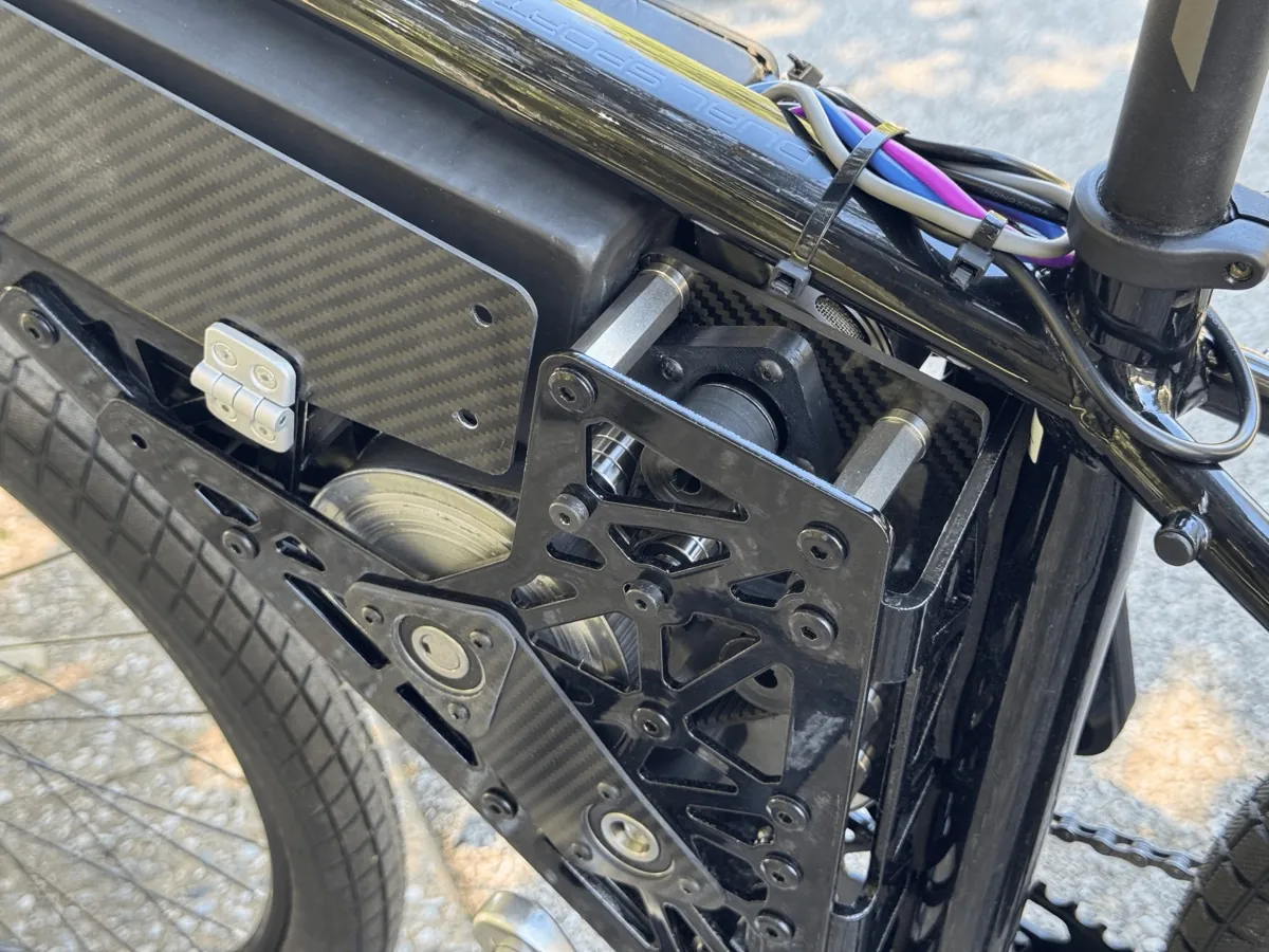
I designed all of the custom parts. The motor mount, the bearing plates and the battery box panels are carbon fiber, cut by an outside shop. The outer plates and the brackets along the seat tube and down tube are powder-coated 5052 aluminum, with the brackets bent on a press brake. The adapter plate on axle 2 is stainless steel. I 3D printed the shaft spacers and the polycarbonate chain idler mount myself. The 48 V, 16 Ah battery sits in a box under the top tube, closed with a door and two draw latches.

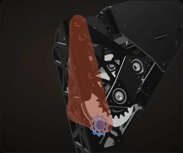
Iteration: the chain idler
The two versions of my CAD: V1 with the jockey wheels on an aluminum flange, and V2, my latest, with a polycarbonate idler mount. Diffing every part between the two files shows that only the chain idler changed. Jockey wheels in blue, the part that carries them in orange; the frame mockup in V2 is hidden so the two match.
V1: two jockey wheels on an aluminum flange
Two 11T jockey wheels on shoulder screws route the chain around the drive sprocket, threaded into a 4.75 mm flange of the aluminum seat tube bracket (orange). One of them only added chain wrap on the big pedaling chainring. The drive ran this way in its first tests on the stand.
The idler mount bent
Problem The idler mount bent
The flange was bent from a flat pattern on a press brake, and about 6 kW of drive bent it out of shape. At 100 N·m on the sprocket the chain pulls the upper jockey with about 4,300 N, 10 mm out from the flange: 32 N·m on a bend that starts to yield at 18.
The fold is drawn larger than life; the chain is drawn in, it is not in my CAD.
V2, my latest: one jockey on a tall printed mount
Fix
V2 carries one jockey, 4 mm further outboard, on a tall 3D-printed polycarbonate mount along the seat tube (orange, see-through); its screw is threaded into the old aluminum flange behind it. The second jockey only added chain wrap on the pedaling chainring, which was not really needed.
Everything else stayed
The motors, both belts, every pulley and both axle stacks are identical in the two CAD files. The only other changes: a polycarbonate battery plate adapter, and the drive-side battery panel moved out 6 mm.
Why the aluminum flange bent
About 6 kW goes through the drive, and all of it reaches the rear wheel through the chain. In V1 that chain wrapped a jockey on a shoulder screw, its center about 10 mm out from a 4.75 mm aluminum flange, right in the flange's top corner. A rough calculation from my V1 CAD shows why the flange gave way.
Calculation How hard does the chain pull on the V1 idler?
| Peak torque at the sprocket | 100 N·m | my build |
|---|---|---|
| Chain sprocket | 20T, 1/2 in pitch | counted in my CAD |
| Chain wrap on the upper jockey (11T) | 122° | measured in my V1 CAD (tangent lines) |
| Jockey center to flange mid-plane | 10.4 mm | measured in my V1 CAD |
- Sprocket pitch radius: 12.7 mm / (2 sin(180° / 20)) ≈ 40.6 mm
- Chain pull: T = 100 N·m / 0.0406 m ≈ 2,460 N. Under motor power it runs from the rear cog, under the upper jockey (the one V2 keeps) and onto the sprocket; the lower jockey sits on the slack side, toward the freewheeling chainring
- Load on the upper jockey: F = 2 T sin(122° / 2) = 1.75 × 2,460 N ≈ 4,300 N, pointing 45° off the line of the flange's bend (both directions from my V1 CAD)
- The part of F at right angles to the bend, 4,300 N × sin 45° ≈ 3,060 N, acts 10.4 mm out from the flange, so it tries to fold the flange about its bend: M = 3,060 N × 0.0104 m ≈ 32 N·m
At full torque the upper jockey carries about 4,300 N, and the flange under it feels about 32 N·m trying to fold it about its bend.
Estimate: static peak torque, no losses. The rear wheel is not in the CAD, so the top run of the chain is taken as level; tilting it 10° either way changes the folding moment by about 5 %.

Calculation How much can the flange take?
| Flange thickness | 4.75 mm | measured in my V1 CAD |
|---|---|---|
| Length of its bend | 63.8 mm | measured in my V1 CAD |
| Upper jockey | 15 mm from the bend, 10 mm from its top end | measured in my V1 CAD |
| Temper | 5052-H32 | the 5052 Fabworks uses, which lists 0.187 in (4.75 mm) sheet |
| 5052-H32 yield strength | 193 MPa | ASM / MatWeb |
- A strip of 5052 b wide and t thick starts to yield at M = σ b t² / 6 and folds right over at σ b t² / 4
- To hold 32 N·m without yielding, the bend needs b = 6 × 32 N·m / (193 MPa × (4.75 mm)²) ≈ 44 mm working together; just to not fold over, 29 mm
- The jockey sits in the flange's top corner. Spreading at about 45° across the 15 mm to the bend, its load reaches about 15 mm of bend below it but only the 10 mm above it: about 25 mm in all
- 25 mm of bend starts to yield at 193 MPa × 25 mm × (4.75 mm)² / 6 ≈ 18 N·m and folds over at about 27 N·m
The corner of the flange sees about 32 N·m, against 18 N·m to start bending it and 27 N·m to fold it over: about 1.2 times the folding moment, so no margin at all at full torque. It starts to yield from about 57 N·m at the sprocket, a bit over half of the peak.
Estimate: no fatigue. The same load also twists the flange by about as much again, which only makes it worse and is left out here. Even if the whole 63.8 mm bend shared the load evenly, it would start to yield at 46 N·m, only 1.5 times the load. The 45° spread is a rule of thumb.

How much load the printed mount takes
In V2 the jockey turns on a McMaster-Carr 91273A403 stainless shoulder screw, threaded into the old aluminum flange of the seat tube bracket 8 mm behind the jockey, and the printed mount holds the screw on the jockey's other side. How much the printed mount carries depends on how hard the chain pulls when I ride. I worked that out from my CAD, then ran a finite element analysis (FEA) of the real parts.
Calculation How hard does the chain pull when I ride it?
| Rider | 77 kg (170 lb), seated | me |
|---|---|---|
| Bike | 13.25 kg, a 2019 Trek Dual Sport 2, plus about 12 kg of e-bike parts (motors, pack, plates, belts, controllers) | 99 Spokes; my CAD and estimates |
| Center of mass | 0.43 m ahead of the rear tire's contact, 0.99 m up | estimate from the frame geometry |
| Drive | two SKP 6465, 150 KV, 50 A each; 16.2 : 1 to the 20T sprocket (40.6 mm pitch radius) | my VESC setup; my CAD |
| Gearing | Shimano HG31 11-32 cassette, 27.5 × 2.4 in tire (708 mm) | Trek |
- Motor torque: Kt = 60 / (2π × 150) = 0.0637 N·m/A, so 2 × 50 A × 0.0637 × 16.2 ≈ 103 N·m at the sprocket, capped at 100 N·m
- Chain pull at that torque: 100 N·m / 40.6 mm ≈ 2,460 N
- Push at the tire: 2,460 N × r(cog) / 354 mm = 157 N in the 11T up to 451 N in the 32T
- The front wheel lifts at m g b / h = 102.5 kg × 9.81 × 0.43 / 0.99 ≈ 440 N of push, well before the tire slips (about 1,760 N)
With me on it, every full-throttle start in the 11T to 28T reaches the motors' 100 N·m before the front wheel lifts (only the 32T lifts first, at 2,410 N). So the riding peak is the same 2,460 N of chain pull, 4,310 N on the jockey.
Estimate: no drivetrain losses and no pedaling, which keeps the pull on the high side.

The printed mount at that load
Calculation How much load can the printed mount take?
| Load on the jockey | 4,310 N at the riding peak (the calculation above): 4,300 N in the chain's plane, 29° above horizontal toward the rear wheel, and 330 N inboard, because the V2 jockey sits 4 mm outboard of the sprocket | the calculation above, with the jockey's position in my V2 CAD |
|---|---|---|
| Printed mount | the V2 idler mount, printed flat in Polymaker PC (FDM) | my CAD; the print photo above |
| Polymaker PC | tensile strength 69.1 MPa along the layers (X-Y) and 52.8 MPa across them (Z); modulus 2,497 MPa. It breaks at 4.8 and 2.7 % strain, so the tensile strength is taken as the yield | Polymaker PC datasheet |
| Poisson's ratio of PC | 0.37 | Polycarbonate |
| Mounting | three M6 bolts through the printed mount, the 3.18 mm drivetrain-side plate and the seat tube bracket's side flange, with the back of the mount resting on the plate; the jockey's shoulder screw threads into the old aluminum flange behind it | my CAD |
- FEA in CalculiX with 10-node tetrahedra of the real parts: the printed mount, the jockey screw and bearing cap, the plate behind the mount and the seat tube bracket (5052 aluminum). The bolted joints are held fixed; where parts touch they can only push on each other, and the solve is repeated until the contacts settle
- At the riding peak the body of the printed mount reaches about 39 MPa
- Safety factor: 69.1 / 39 ≈ 1.8 along the layers, 52.8 / 39 ≈ 1.3 across them
- Mesh check: going from 1.2 to 0.7 mm elements (169,000 to 451,000 nodes), the body's peak stayed at 39 MPa
At the riding peak, 4,310 N on the jockey, the body of the printed mount has a safety factor of 1.8 along the print layers (1.3 across them). FDM prints are anisotropic and never perfectly fused, so that margin matters.
FEA estimate from my CAD, not a test: linear elastic, with the datasheet's strength for solid test bars; printed parts vary with the print settings.

What the first rides found
After the first rides I took the drive apart. The problems chained into each other, and the second belt took the hit.
Problem Axial play in the axles
The axles had play along their length, enough for a bearing to slip out of its seat in the carbon fiber plate.
Fix
I added spacers to take the play out.
Problem The second belt misaligned and stripped
The spacers bent the outer aluminum plates slightly. The flanges bent on the press brake are not exactly 90 degrees either. Together they pulled the second belt out of line, and on a top-speed run to 35 mph it stripped a section of its teeth.
This is the harder-working of the two belts: at 100 N·m on the sprocket it pulls about 1,750 N, 3.6 times the first belt (from the pulley sizes in my CAD).
Next time Never fixed: a tensioner for the second belt
I never fixed it. The belt failed right before winter, and I was working on my college applications and did not have time to work on the bike.
The fix it needs is a tensioner on the second belt, the belt that carries more torque.


Results
Before the second belt failed, it rode at about 35 mph with about 20 miles of range, and 100 N·m at the sprocket.
More pictures


