← All projectsPennApps XXVSep 2024
Braille Printer
Low-cost gantry prototype
A low-cost braille printer prototype built on a 2020 extrusion gantry.

In 36 hours at PennApps XXV, my team of four built a prototype braille printer. I designed the gantry: a frame of 2020 aluminum extrusion with stepper-driven X and Y axes. The X axis runs on a GT2 timing belt. We ran out of belt for the Y axis, so I rigged it with dental floss wound on spools.
A servo on the X carriage swings a round-nosed pin down onto paper lying on a die plate with 4,050 dimples, one for every dot position on the page. The pin presses the paper into a dimple, and the dot stands up on the other side.
The printer was not completely finished, so it stays a concept: the writing below is animated on our CAD.
How it writes, dot by dot
Our CAD, writing a word as you scroll: the gantry moves on its belt and floss, the servo swings the pin down its real arc, and the page comes out at the end to be read.
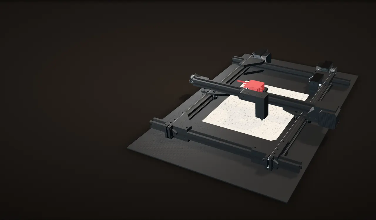
A word
Braille writes each letter as a cell of six dot positions, two columns of three. As you scroll, the word types itself and each letter becomes its cell.
Capital letters take a capital sign, dot 6, in front. PennApps is 10 cells and 28 dots.
Written from the back
The pin pushes the paper down into the die, so every dot stands up on the far side of the sheet, the side you read once the page is turned over.
So a line has to be embossed as its mirror image: the first cell goes on the right, and the two columns of every cell swap. The orange rings mark where the 28 dots will go.
Line up on the first dot
Two axes carry the pin. Y slides the whole gantry beam along the side rails, pulled by floss wound on a spool at each side. X slides the servo carriage along the beam on a GT2 belt.
The pin stops about 4 mm to one side of the dot, because it does not come straight down.
Row one: an arc, not a plunge
At each dot the servo turns 3.3°. The arm pivots on the servo shaft 86 mm from the pin's nose, so the nose comes down on an arc: it drops 2.9 mm and moves 4 mm sideways, 0.9 mm of that inside the dimple. It presses the paper in and swings back up.
Row two, on the way back
This path writes one row of dots across the whole line, steps Y by 2.34 mm and comes back. Y moves the entire gantry, so it moves only three times per line, while X, which moves only the small carriage, does the running.
Row three
The last row holds dots 3 and 6, including both capital signs. Every dot lands on one of the die's dimples: 2.34 mm apart inside a cell, 6.22 mm from cell to cell.
Turn it over
Out of the printer and turned over, the dots stand up and the word reads left to right.
My team's real CAD: the gantry, both drives, the servo arm and pin on their real arc, and the die grid the dots land on. The word, the path, the speeds, the paper and its dots are the animation's, and so is the floss, which is not in the CAD (the photos show it). The swing starts from the arm's position in the CAD, 2.3 mm above the page, and the animation stays inside the area the pin reaches in the CAD. Angles and distances are computed from the CAD, ignoring the paper's thickness.
How it works
The paper lies on the die, a plate covered in small dimples, one for every dot position on the page. The gantry carries the pin over one dimple at a time: the Y axis slides the whole gantry beam along the frame, and the X axis slides a carriage along the beam. At each dot a servo swings the pin down and presses the paper into the dimple, so a dot stands up on the other side of the sheet.
The gantry
I designed the gantry. Four 400 mm lengths of 2020 aluminum extrusion make the frame. Each side rail carries a carriage plate on four V-wheels, and the gantry beam, a fifth 400 mm extrusion, bolts across the top of both side carriages. A third carriage runs along the beam and carries the servo.
Three steppers drive it: one at the end of the beam for X, and one at the end of each side rail for Y, so both ends of the beam are pulled at once.


Out of belt: dental floss
Problem Out of belt
We ran out of timing belt. The X axis had its GT2 belt, but there was not enough left to run the Y axis the same way.
Fix
I rigged the Y axis with dental floss instead. Each side rail has its own stepper with a spool on its shaft, so both ends of the gantry beam are pulled at once.
The spool has two grooves, each 4 mm wide, on a 15.5 mm radius drum between 20 mm flanges: about 97 mm of travel per turn (computed from the CAD). Small holes through the flanges tie the floss off. At the far end of the rail, two 7 mm rollers sit one above the other, level with the top and the bottom of the drum.

In the photos of the assembled machine, the floss shows as a thin white line along both side rails.

The gantry, axis by axis
Our CAD moving along its real axes. The motor shafts, the belt pulley, the floss spools and the idler rollers turn with the travel they drive.
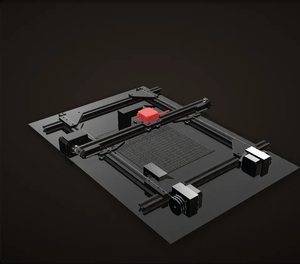
The frame
Four 400 mm lengths of 2020 extrusion on a base sheet. The beam rides on two side carriages, each on four V-wheels, and the servo carriage runs along the beam.
Y: the whole beam, on floss
Scroll and the Y axis runs. A stepper at each side winds dental floss on a spool, and the floss pulls the gantry beam, with everything on it, along the side rails.
Two motors, one per side, pull both ends of the beam together.
The spool
Cut through the spool's axis: two grooves, each 4 mm wide, on a 15.5 mm radius drum between 20 mm flanges. One turn is about 97 mm of travel. Small holes through the flanges tie the floss off.
At the far end of the rail, two 7 mm rollers sit one above the other, level with the top and the bottom of the drum, so a run of floss leaving either side of the drum stays level along the rail.
X: the carriage, on a belt
The X motor sits at the end of the beam and rides with it. It drives a GT2 timing belt through a 20-tooth pulley, 40 mm of travel per motor turn, with idler bearings at both ends of the beam.
Both together
Y picks the line and the row of dots, X the dot along it. Here the carriage runs a rectangle, Y first, then X, and the orange line traces the pin over the die.
My team's CAD on its real axes. Travel per turn is computed from the CAD: 20 teeth of 2 mm for the belt pulley, a 15.47 mm drum radius for the spools. The floss (white) and the trace (orange) are drawn; the floss and the belt are not in the CAD.
The embossing head and the die
A servo, an arm and a pin, and a plate full of dimples. Scroll to swing the pin into one of them.
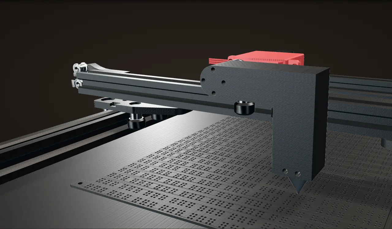
The head
A servo lies on its side on the X carriage (a DS3225MG in our CAD). An arm bolted to its horn carries the pin, whose tip is a round nose 1.6 mm across, the same size as a dimple at the surface.
Down on an arc
The cut runs through the pin and one row of dimples. As you scroll, the servo turns the arm. From 2.3 mm above the die, the nose touches the surface at 2.6° and reaches the bottom of the dimple at 3.3°.
Four millimetres sideways
The arm pivots 86 mm from the nose, so the nose moves 4.05 mm along the die on the way down, 0.9 mm of it inside the dimple. To land on a dot, the pin has to start that far to one side of it.
The die
The die in our CAD is a 1.6 mm plate, 206 by 249 mm, with 4,050 dimples: 25 lines of 27 cells, six dots per cell. Each dimple is 1.6 mm across and 0.6 mm deep.
Dots are 2.34 mm apart both ways and lines 10 mm apart. Cells are 6.22 mm apart in groups of three, and the groups repeat every 21 mm, so from the last cell of one group to the first of the next is 8.56 mm.
My team's CAD, cut through the pin's plane; the arm turns about the servo's real shaft axis. The orange arc, the dimension lines and the labels are drawn, and every number is computed from the CAD.
Calculation Why the pin parks 4 mm short of the dot
| Servo shaft to the centre of the pin's nose, across | 52.5 mm | measured from our CAD |
|---|---|---|
| and down | 68.1 mm | measured from our CAD |
| Nose above the die, as the CAD is posed | 2.34 mm | measured from our CAD |
| Dimple depth | 0.6 mm | measured from our CAD |
- Arm: √(52.5² + 68.1²) = 86.0 mm, leaning atan(52.5 / 68.1) = 37.6° off vertical
- The nose moves at right angles to the arm, so near this pose it goes 68.1 / 52.5 = 1.3 mm sideways for every 1 mm down
- Down to the bottom of a dimple: 2.34 + 0.6 = 2.94 mm, which the arc reaches at a 3.3° turn
- Sideways on the way down that arc: 4.05 mm (1.3 × 2.94 = 3.8 mm by the straight-line estimate, which leaves out the arc's curve)
Each dot takes a 3.3° swing that also carries the pin about 4 mm along the line, so the carriage has to stop about 4 mm before every dot.
Geometry of the CAD only, ignoring the paper's thickness.
Laying out the die
Saturday night the die went into Fusion 360 under the gantry. The screenshots show the whole grid of dimples dimensioned to the frame on every side, with the gantry beam and the servo carriage plate over it.
The grid in the CAD groups its cells in threes, 21 mm apart, which shows as the wider gaps between every third cell in the screenshots.
Calculation Does the die match standard braille?
| Die: dots, cells (in a group), lines apart | 2.34, 6.22, 10 mm | measured from our CAD |
|---|---|---|
| Die: dimple across, deep | 1.6, 0.6 mm | measured from our CAD |
| Die: lines, cells per line | 25, 27 | measured from our CAD |
| Standard: dots, cells, lines apart | 0.092, 0.245, 0.400 in | NLS Spec. 800 (BANA) |
| Standard: dot across, high | 0.057, 0.019 in | NLS Spec. 800 (BANA) |
- Dots: 0.092 in × 25.4 = 2.34 mm, the same as the die
- Cells: 0.245 in × 25.4 = 6.22 mm, the same as the die inside each group of three
- Lines: 0.400 in × 25.4 = 10.16 mm, 0.16 mm more than the die
- Dot: 0.057 in × 25.4 = 1.45 mm across and 0.019 in × 25.4 = 0.48 mm high, so each dimple is 0.15 mm wider and 0.12 mm deeper than a standard dot
- A full page: 25 lines × 27 cells = 675 cells, and 675 × 6 = 4,050 dimples
The die's dot and cell spacing match the braille standard to a hundredth of a millimetre, its lines are 0.16 mm closer, and every dimple has room for a full-size standard dot.
Compares the die's layout in our CAD with the standard; no embossed page was measured.


The CAD
Our CAD of the whole printer, turned by the scroll.
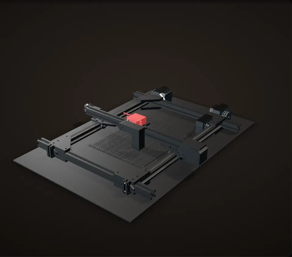
The whole printer
The frame, the gantry, the head and the die, as we modelled them in Fusion 360.
The die
The die plate: 4,050 dimples in 25 lines of 27 cells.
The head
The servo, the arm and the pin on the X carriage.
My team's CAD; screws dropped for the web, shapes unchanged.
36 hours
Sat 2 a.m.
The frame on the floor
The 2020 extrusions laid out on the carpet with calipers and a box of hardware, the frame sketch open on the laptop. Six minutes later, three sides were bolted up.
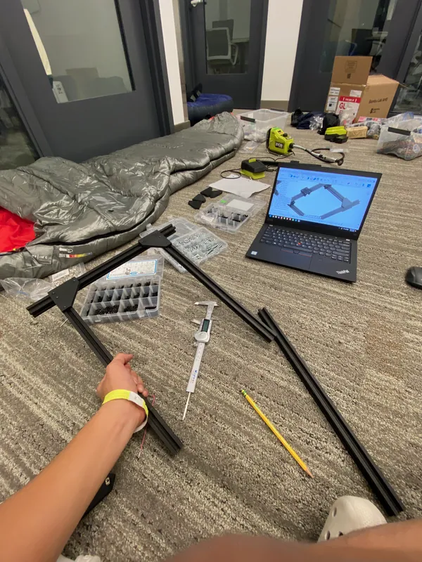
Early Saturday: extrusion, calipers and the frame sketch on the laptop 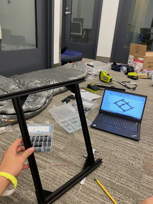
Three sides of the frame bolted up, with the gantry CAD on the laptop Sat 4 a.m.
Printing parts
Parts on the printer in the middle of the night.
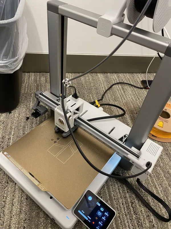
4:21 a.m. Saturday: printing parts Bench test
One axis on its own
We also ran a single axis on its own on the table: one extrusion, a stepper at one end and a carriage plate on its V-wheels, with a laptop and a nest of wiring beside it.
One axis on the bench: the carriage runs along the extrusion Another run of the bench axis Sat 10 p.m.
The die in CAD
The dimple grid laid out under the gantry in Fusion 360.
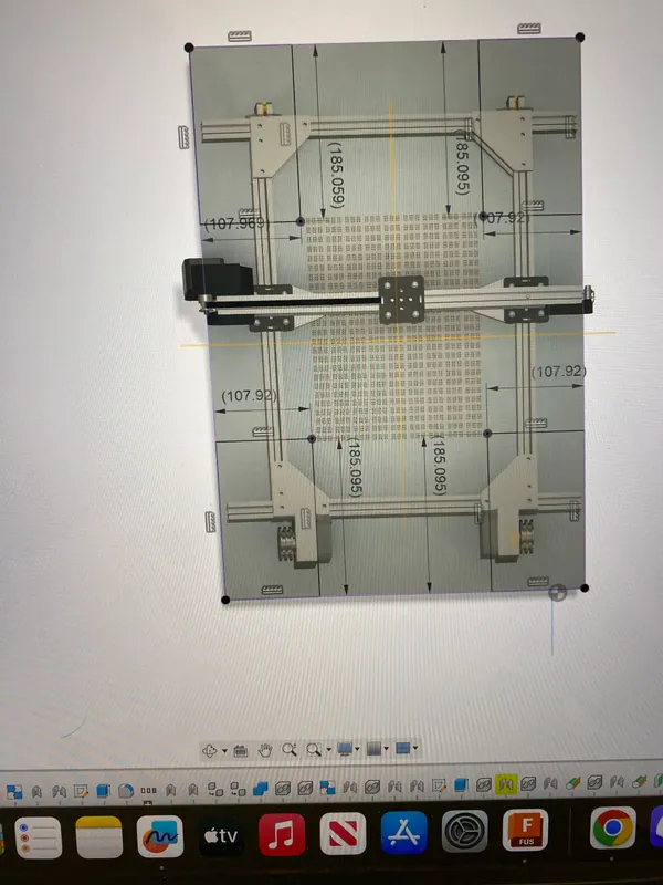
The whole machine from above in Fusion 360, with the dimple grid under the gantry Assembled
On the floor
The gantry together on the carpet: both Y motors at the far end, the beam across the side rails, the servo on its carriage, and floss along both rails.
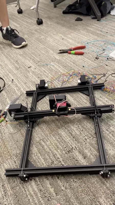
The assembled gantry on the floor Sun 10 a.m.
Wired up on the desk
The machine on a classroom desk with paper under the gantry, a microcontroller board, red driver boards and a lot of jumper wires beside the frame.
From the gantry down to the boards and wiring The machine from above the electronics end


