← All projectsConceptAug 2024
VTOL Tailsitter
Designed in SolidWorks
A tailsitter VTOL aircraft I designed to learn SolidWorks, based on an MIT tailsitter.

A tailsitter stands on its tail, takes off straight up like a drone, then pitches over and flies on its wing like a plane. I designed this one in SolidWorks to learn the program, based on the tailsitter aircraft from MIT's 2023 research.
It is a 360 mm flying wing with a round fuselage, two fins and two elevons, pulled by two brushless outrunners with 3 inch DALPROP T3045 props. It is a concept: I planned to 3D print it, and the CAD covers the airframe, the motors and the props.
Take-off, step by step
My CAD on a launch pad. Scroll to fly it: it spools up, climbs straight up, hovers, pitches over and flies away on its wing. The props, motor rotors and elevons turn about their real axes in the CAD, and the readout keeps the clock.
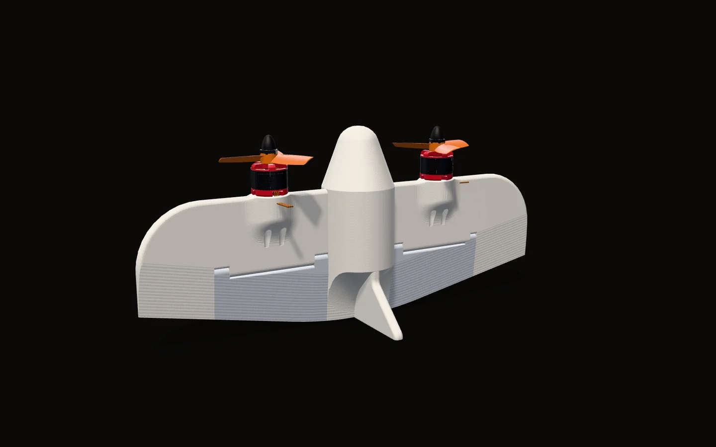
Standing on its tail
A tailsitter has no landing gear and no tilting motors. It stands nose up, props pointing at the sky.
In my CAD the trailing edges of both fins and of the wing root end on one flat plane, so the aircraft can stand on them.
Straight up
Both props spin up and lift the whole aircraft like a two-rotor drone. It climbs with its nose at the sky and its wing edge-on to the ground.
The two props turn in opposite directions (the arrows), so the reaction torques they put on the airframe cancel and it does not start to spin about its vertical axis.
Hovering: where the control comes from
In a hover there is no airspeed, so the only air moving over the wing is the propwash. Each elevon sits right behind a prop.
The right prop disc covers 39 to 115 mm out from the centreline and the right elevon 30 to 120 mm (measured in the CAD), so the elevon sits in the wash across the whole disc. Swinging it bends that wash, which is how a tailsitter steers before it has any speed.
Pitching over
At 4 seconds in this illustration the transition starts. The elevons go trailing edge down and the nose tips toward the horizon. As it gains speed, the wing starts to carry the weight instead of the props.
Flying on the wing
Now it is a flying wing. The wing carries the weight, the props only push it forward, and the same two elevons steer it.
An illustration on my real CAD: the aircraft, its props, motor rotors and elevon hinges are the model, and each turns about its real axis. The flight itself (times, heights, speeds, angles and elevon deflections) is scripted to show the sequence. It is not flight data: this aircraft was never built or flown. The prop discs, the spin arrows, the air column and the span bars are drawn in.
Why a tailsitter
I made this project to learn SolidWorks. I based it on the tailsitter aircraft from MIT's 2023 work on planning fast, acrobatic flight for tailsitters (MIT News), and in my repo's README I called it "a VTOL Tailsitter I plan on 3D Printing".
A tailsitter is one of the simplest ways to get a plane that takes off and lands vertically. There is no runway, no landing gear and no motor that tilts. The whole aircraft points its nose at the sky to take off and land, and tips over to fly forward. The same two props lift it in a hover and push it in forward flight, and the same two elevons steer it in both.
The catch is that one airframe has to work in two very different regimes: hanging on its props at zero airspeed, and flying on its wing. In this layout the elevons sit directly behind the props, where there is moving air over them even in a hover.
Calculation How much of each elevon is behind its prop?
| Right prop disc, out from the centreline | 38.9 to 114.6 mm | measured from the CAD |
|---|---|---|
| Right elevon, out from the centreline | 29.5 to 119.5 mm | measured from the CAD |
- The disc lies inside the elevon's span: 29.5 < 38.9 and 114.6 < 119.5 mm
- Disc: 114.6 − 38.9 = 75.7 mm across. Elevon: 119.5 − 29.5 = 90.0 mm
- Share of the elevon's span straight behind the disc: 75.7 / 90.0 = 0.84
About 84 % of each elevon's span sits straight behind its prop, so most of the surface that steers in a hover is in the propwash.
Geometry only: behind a real prop the wash narrows and swirls, so this is the share in line with the disc, not a measured airflow.

The airframe
How the airframe is built, from the CAD. It turns slowly as you scroll.
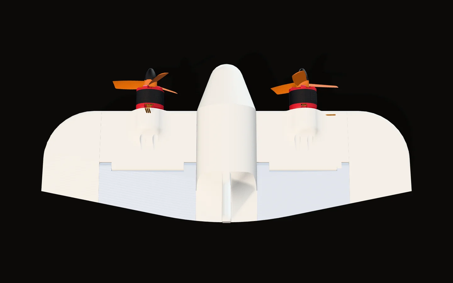
Planform
A 360 mm span and 158 mm from nose to tail (CAD). The leading edge is straight, with rounded tips. The trailing edge sweeps forward about 11 degrees toward the tips, so the chord shrinks from 108 mm next to the fuselage to about 90 mm near the tips.
A flat-plate wing
The wing is a flat plate 8 mm thick with a fully rounded leading edge. Over the elevons and the outer trailing edge it tapers to a thin wedge. The cut here runs 50 mm right of the centreline, through the right inner panel and elevon.
Seven bodies
In SolidWorks the airframe is one part made of seven solid bodies: the fuselage with both fins and the wing root, two inner panels that carry the motor nacelles, two outer panels and two elevons.
The elevon hinge
Here the bodies are pulled apart a little. Each elevon has a rounded nose that turns inside a cove cut into the wing. A 2.7 mm bore runs 300 mm along the hinge line through the fuselage, the inner panels and the outer panels, and each elevon has a knuckle at each end with a 2.0 mm bore on the same line.
The pin itself is not in the CAD.
Fins
Two fins stand 64 mm above and below the wing, with 45 degree swept leading edges filleted into the fuselage. Their flat trailing edges end on the same plane as the wing root: the tail it stands on.
The wing in numbers
Measured from above in the CAD, the outline gives the numbers a wing is usually described by: its area, its aspect ratio (how long and slender it is) and how much of it is control surface.

Calculation How big is the wing?
| Span | 360 mm | measured from the CAD |
|---|---|---|
| Area seen from above (fuselage and nacelles in) | 35,970 mm² | measured from the CAD |
| Both elevons, seen from above | 7,870 mm² | measured from the CAD |
- Mean chord = area / span = 35,970 / 360 = 100 mm
- Aspect ratio = span² / area = 360² / 35,970 = 3.6
- Elevon share = 7,870 / 35,970 = 22 % of the wing
A short, broad wing: aspect ratio about 3.6 and a mean chord of about 100 mm, with about a fifth of its area in the two elevons that steer it both in a hover and in forward flight.
Areas from the top-view outline of the airframe in the CAD, props and motors left out. The fins are edge-on from above and add nothing.

Motors and props
The propulsion in the CAD: two brushless outrunners, each with a three-blade prop.
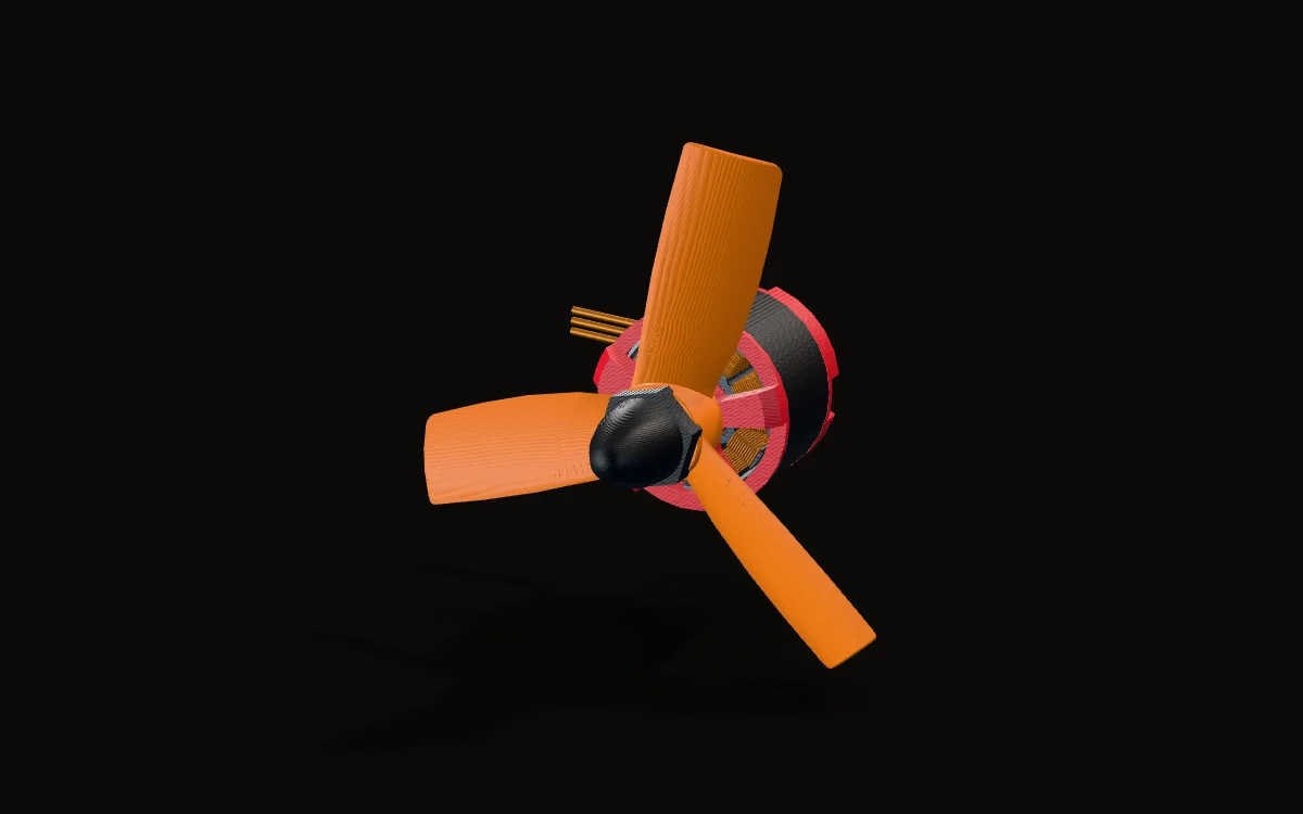
Props: DALPROP T3045
The props are DALPROP T3045s: 3 inch diameter, 4.5 inch pitch, three blades. The CAD part carries the name, and its blades measure 75.7 mm tip to tip.
Inside the motor
The motors are a brushless outrunner model, cut here through the right motor's axis. The can with its 14 magnets spins around a 12-tooth stator, and the prop is fixed to the can. The stator measures 22 mm across and 13 mm tall, the can 28 mm across, and the shaft is 3 mm (all measured in the CAD).
Outrunners are usually named by stator size, diameter then height, so in that naming this is a 2213-size motor.
Where they sit
The motor centres are 153.5 mm apart. Each prop spins about 27 mm ahead of the leading edge, and its tips pass 9 mm from the fuselage (CAD).
Learning SolidWorks: v1 to v7
My repo keeps every version of the airframe part, so you can watch the design, and my SolidWorks, grow. The STEP files of v3 to v7 were exported on Aug 15 and 16, 2024.
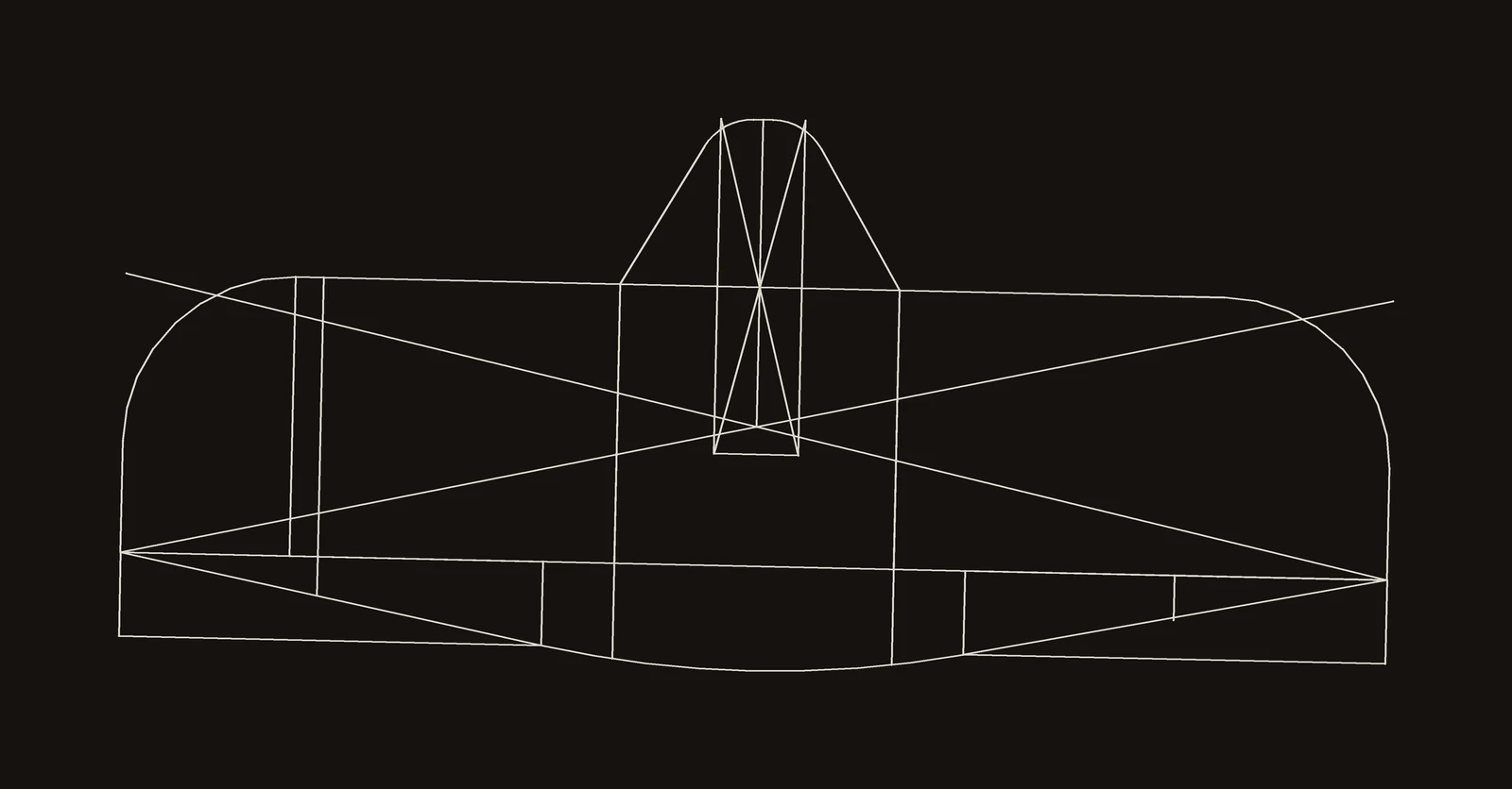
v1: the first sketch
Problem The first sketch was not square
In v1 the lines are not level or symmetric: the leading edge drifts about 6 mm across the span, and the two wingtips differ.
Fix
v2 redraws the same outline level and symmetric. The 360 x 158 mm outline it set stayed the same through every later version.
v2: redrawn
v2 is level and symmetric, with true arcs at the tips, boxes for the two motor nacelles, the nose and the lines where the elevons split off.
v3 (Aug 15): the first solid
The outline became solid bodies: the round fuselage, two inner panels with round nacelles, and flat 8 mm outer panels and elevons. No fins yet.
v4: tapering the trailing edge
The trailing edge tapers to a wedge, on the right side first.
v5: both sides, nacelles and fins
Both sides taper now, the nacelles blend into the wing with fillets, and the fins arrive as plain rectangular blocks 64 mm above and below the wing.
v6: swept fins
The fins are cut to a 45 degree swept leading edge and filleted into the fuselage.
v7 (Aug 16): the hinge
The elevons get their rounded noses, the coves they turn in, a knuckle at each end and the pin bores.
The assembly
v7 with the two motors and props: the model the rest of this page is built on.
Where it stands
The CAD stops at the airframe, the motors and the props. There are no servos or pushrods for the elevons, no battery, speed controllers or flight controller, and no hinge pins. In the repo's README I called it "very much a WIP (CAD not done)".
My SolidWorks screenshots from February 2025 show the fuselage with an open, round front instead of the nose cone in the August 2024 files.
Colours
The STEP export carries no colours, so every part here is coloured by what it is: the motors red and black and the props orange, as in my SolidWorks model, and the airframe a white printed plastic, since I planned to print it.
Every dimension on this page is measured from my CAD. The CAD files, every airframe version from v1 to v7, are on GitHub.
