← All projectsFIRST Tech ChallengeFeb to Mar 2026
FTC DECODE Two-Sided Intake
Robot concept for the 2025-26 DECODE game
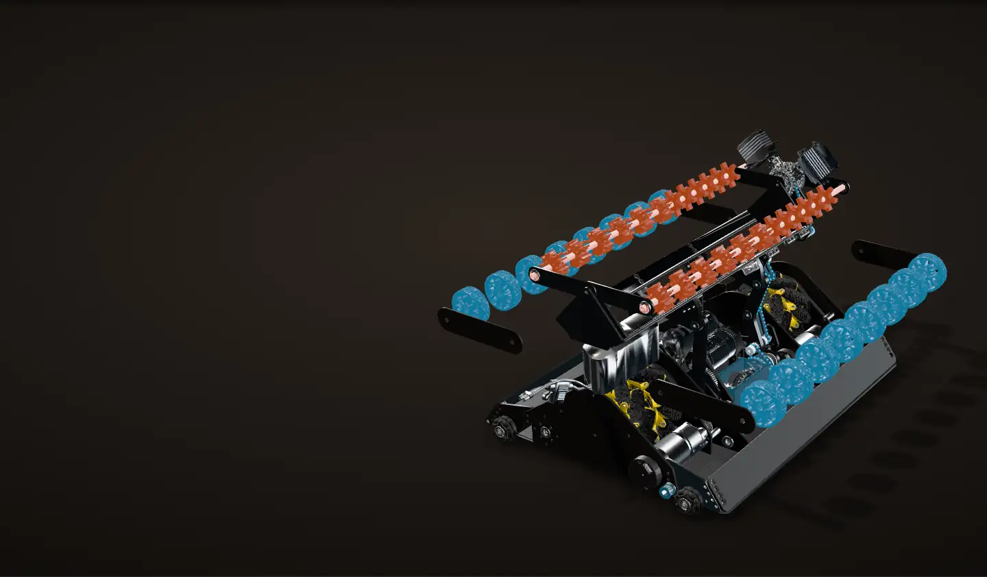
An FTC DECODE robot concept that intakes from both sides, three balls wide on either side.


A robot concept for the 2025-26 FTC DECODE game that picks up balls from either side, three at a time. One 4-bar linkage swings out to whichever side is intaking and comes back to the middle to hand the balls up to a turret shooter. Two motors run both the 4-bar and the rollers on it through a differential power take-off: spin them the same way and one thing happens, spin them opposite and the other does.
It was never built. I could see construction, friction and slop problems coming, it would not have gained much on a real robot, and the World Championship deadline was close, so we improved the robot we already had instead. The one piece of real hardware is a test chassis for its collinear mecanum drivetrain: all four mecanum wheels in a line down the middle.
The differential PTO
The heart of the concept: two motors drive both the 4-bar and all four rows of intake wheels through a differential power take-off (PTO). Two motors, two outputs, and which output moves depends only on how the motors turn relative to each other. Yellow is the motor input, orange is carrier 1's path to the 4-bar, blue is carrier 2's path to the rows of wheels, and whichever is moving lights up.
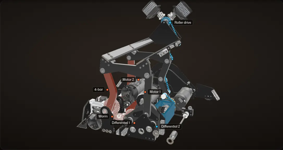
Two motors, two differentials
Motor 1 turns the front shafts of both bevel differentials, one of them the other way through a row of gears; motor 2 turns both back shafts. Carrier 1 turns the worm, and with it the 4-bar. Carrier 2 drives the belts up to F, the top of the 4-bar, for the two rows on it, and a side belt toward the two outer rows.
Same way: the wheels run
In close on the gearbox. Same way, same speed: carrier 1 stays still and carrier 2 turns, so all four rows of wheels run and the 4-bar holds. Carrier 2 turns at 2,175 RPM and F, the top of the coupler, at about 2,750 RPM, no load.
Opposite ways: the 4-bar swings
Opposite ways: carrier 2 stays still and carrier 1 turns. The 4-bar swings and the wheels stop. Both motors swing the 4-bar: about 155 RPM (930°/s) at no load, which would take it from one endstop to the other in about 0.21 s.
One motor: some of both
Anything in between does some of both. With one motor running and the other still, each carrier turns at half speed: the 4-bar swings back at about 78 RPM while the roller drive turns at about 1,370 RPM.
Inside the differentials
Cut open at their axes and running the same way again. In differential 1 the two 14-tooth side gears turn opposite ways, so the 28-tooth spider spins in place and the carrier holds. In differential 2 both side gears turn together, and the whole carrier turns with them.
Seen from the front, with the front drive pod cut away. Every gear, carrier, spider, pulley and link turns about its axis in the CAD by the ratios its tooth counts give; the readout shows real no-load speeds, computed from the tooth counts. The dots on the belts are an overlay. How F is split to the two roller shafts is not modelled in the CAD, so the shafts simply turn with F. Carrier 2's side belt, lit with it, heads for the two outer rows.
The idea
DECODE robots pick up 5 in balls from the floor and shoot them into a goal. This concept picks them up from both sides of the robot, three balls wide on either side. The cycle:
- A 4-bar linkage swings out to whichever side is intaking.
- To transfer, it comes back to the middle, where walls limit the range of the linkage.
- A pusher pushes the balls to one side.
- Rollers on the 4-bar push them up into the shooter.
- The shooter is a turret, turned by four Melonbotics Super Servos on the inside of a ring gear.
The main mechanism is the differential power take-off (PTO) that drives the intake, animated at the top of this page. Two motors feed it, and it has two outputs: the rotation of the 4-bar, through a worm gear, and the spinning of the four rows of intake wheels. Spin the two motors the same way and one output moves; spin them opposite ways and the other one does. Because the rollers ride on the moving 4-bar, their drive climbs up through the linkage on five belt stages to F, the top of the linkage, where it is split to both rollers. The sections below follow the power from the motors to the wheels, with the CAD moving as you scroll.

The concept in CAD
The whole robot as modelled, turning as you scroll. The outer plates and the side walls are left out so you can see in.
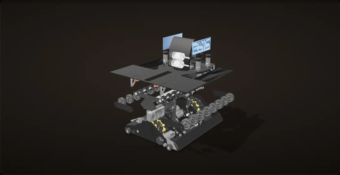
18 inches each way
457 mm (18.0 in) each way, the full FTC starting size, and it uses every motor FTC allows: eight.
A collinear mecanum drivetrain
A collinear mecanum drivetrain: the four drive wheels sit in one line down the middle, each on its own goBILDA 5203 drive motor (3.7:1, 1,620 RPM).
The intake between the wheel pairs
The intake gearbox sits between the two wheel pairs, with two bare goBILDA 5000 motors for the intake PTO, and the 4-bar stands in its transfer position above it.
The turret
The turret is on top toward the back, with two more 5000 motors on it for the flywheel.
Screws, nuts and washers are left out; every other part is the CAD as modelled.
One 4-bar, two sides
The intake is a 4-bar linkage low in the middle of the robot, between the two wheel pairs. There are two linkages, one near the front and one near the back, with a full-length bar across the top of both: the coupler.
In the CAD the ground pivots A and B are 90.0 mm apart, both side links are 90.0 mm between their pins, and the coupler pins C and D are 100.0 mm apart. Nearly a parallelogram, so around the middle the coupler mostly slides sideways instead of rotating. Toward the ends of its travel the links fold and the coupler tips down toward the floor.
The CAD holds the linkage in its transfer position, standing straight up in the middle. From there it swings out on each side until the linkage comes down on the carbon fiber floor plate: the floor plate is its endstop on both sides.

Calculation How far does the 4-bar swing?
| Pins A, B, C, D (seen from the front) | A (183.6, 60.0), B (273.6, 60.0), C (178.6, 149.9), D (278.6, 149.9) mm | measured from the CAD |
|---|---|---|
| Top of the carbon fiber floor plate | 10.0 mm above the floor | measured from the CAD |
| End of the linkage below its outboard pin | 7.5 mm (the ends are rounded about the pins) | measured from the CAD |
- The linkage lands on the plate when its outboard coupler pin is 10.0 + 7.5 = 17.5 mm above the floor.
- Right: solving the linkage for D at 17.5 mm puts the driven link at 10.5° from horizontal, with C at (272, 76) and D at (353, 17.5).
- Left: the pins are mirror images about the robot's centre line (A and B 45 mm either side of it, C and D 50 mm), so C comes down to 17.5 mm with the driven link at 208.2°, 28.2° below horizontal on the other side.
- Travel: 208.2° − 10.5° = 197.7°.
- At either stop the middle of the coupler is 84 mm out to the side and 103 mm lower than at transfer, and the coupler is tilted 36°.
- At the 4-bar's top speed through the PTO, about 932°/s (worked out below), stop to stop takes 197.7 / 932 = 0.21 s.
Almost 198° of swing between the two stops on the floor plate, so one linkage reaches the floor on either side of the robot.
Geometry measured from the CAD; the time is a no-load estimate, so a loaded 4-bar is slower.
The driven side turns through a goBILDA 28:1 worm gear set: the 28-tooth worm wheel is on the driven link's pivot shaft at A, and the worm below it is driven by the PTO.
Out to both endstops
The linkage from the CAD, cut just behind its front links and seen straight down the robot's length. The driven link turns about A; the passive link and the coupler follow from the pin positions.
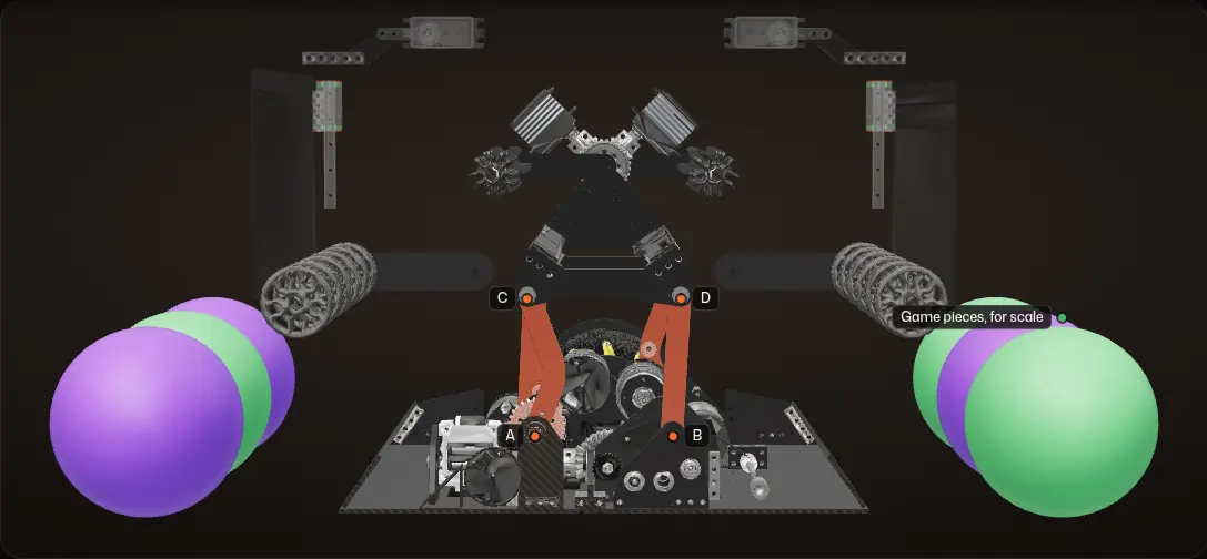
Transfer
Standing straight up in the middle, as the CAD holds it: the driven link at 93.2° from horizontal. To transfer, the linkage comes back here, where walls limit its range.
Out to the right endstop
Swung out to the right, the driven link comes down to 10.5° before the end of the linkage lands on the carbon fiber floor plate. By then the coupler is 84 mm out and 103 mm down, tilted 36°.
All the way across
The same linkage swings back through the middle and out to the same stop on the left: the floor plate again, with the driven link at 208.2°, 28.2° below horizontal. The coupler is 84 mm out, 103 mm down and tilted 36° the other way: 197.7° of travel from one endstop to the other.
Back to transfer
And back to the middle, where the rollers on the 4-bar push the balls up into the shooter.
Cut faces are hatched. The floor plate lights up while the linkage sits on it. The side walls, the two outer rows of 48 mm wheels (fixed to the chassis) and the arms on top of the coupler are drawn see-through; the arms are set by their own servos and stay in their CAD position here. The balls are 5 in DECODE game pieces for scale, not part of the CAD. Endstops and travel are measured from the CAD.
How the PTO is built
All from the CAD:
- Each motor is a bare goBILDA 5000 motor with a 9-tooth pinion, driving through a 48-tooth idler into a 24-tooth gear on a differential shaft: 9:24 overall.
- There are two bevel differentials side by side. In each, a 28-tooth bevel spider turns on a cross pin inside a carrier, between two 14-tooth side gears, one on a front shaft and one on a back shaft.
- The two differentials are tied together twice: at the front by four 24-tooth gears in a row (three meshes, so the two front shafts turn opposite ways), and at the back by a 30-to-30-tooth belt (same way).
- Motor 1 drives the second differential's front shaft; motor 2 drives the first differential's back shaft.
A differential's carrier turns at the average of its two side gears. Following the gears from each motor to each side gear gives, computed from the tooth counts:
carrier 1 (4-bar)   = (9/48) x (motor 2 - motor 1)
carrier 2 (rollers) = (9/48) x (motor 1 + motor 2)
Carrier 1 has a 28-tooth bevel on its face that drives a 14-tooth bevel on the worm shaft, so the worm turns twice as fast as the carrier and the 28:1 worm set turns the 4-bar at carrier 1 / 14. Carrier 2 carries the 48-tooth pulley that starts the roller drive.

Calculation How fast does each output turn?
| Intake motor, no-load speed | 5,800 RPM at 12 V | goBILDA 5000-0002-0001 |
|---|---|---|
| Motor to differential shaft | 9T pinion, 48T idler, 24T gear | counted in the CAD |
| Each differential | two 14T side gears, a 28T spider | counted in the CAD |
| Carrier 1 to the worm shaft | 28T bevel to 14T bevel | counted in the CAD |
| Worm set | 28:1 | goBILDA 3204-0001-0002 |
| Carrier 2 to F | 48T to 12T, 12T through the joints, 12T to 38T | counted in the CAD |
| Carrier 2 to G, toward the outer rows | 52T to 12T | counted in the CAD |
- Each differential shaft: 5,800 × 9/24 = 2,175 RPM (the 48T idler only turns the direction around).
- Opposite ways at full speed: carrier 1 = (9/48) × (5,800 + 5,800) = 2,175 RPM, carrier 2 = 0.
- Worm shaft: 2,175 × 28/14 = 4,350 RPM, so the 4-bar turns at 4,350 / 28 = 155 RPM, or 932°/s.
- Same way at full speed: carrier 1 = 0, carrier 2 = 2,175 RPM, and F = 2,175 × 4 × 12/38 = 2,747 RPM.
- The side branch turns with it: G and the 20T pulley at the front of the robot run at 2,175 × 52/12 = 9,425 RPM, and the intended 6:1 belts on the outermost sides bring the outer rows down to about 1,570 RPM (Four rows of wheels).
All of both motors' speed goes to one output or the other: up to 155 RPM at the 4-bar, or up to about 2,750 RPM at F, which drives both rollers, and about 1,570 RPM at the outer rows.
Computed from tooth counts at no load; under load both are slower.
Motor 1 faces the front of the robot and motor 2 faces the back. "Same way" here means both output shafts turn the same way seen from the front, which is opposite directions for the motors themselves.
The belt path
Problem Power to a moving linkage
The rollers ride on top of the 4-bar, and the coupler under them moves: sideways, down and with a small tilt. Their drive has to come from carrier 2, which sits still in the gearbox between the wheel pairs.
Fix
A chain of five GT2 belt stages up the passive side of the 4-bar, with a pulley on the axis of every joint the belts cross. Each belt runs between two pulleys on the same link, so no belt changes length as the linkage moves.

Every pulley from B to E has 12 teeth, and that is what makes the chain work. A belt between two equal pulleys passes the speed straight through a joint: the pulley on the far side turns at the same absolute speed as the one on the near side, however fast the link between them swings. So the only ratios are the 4:1 at the bottom and the 12:38 at the top, and the roller drive at F turns at 4 x 12/38 = 1.26 times carrier 2 at any 4-bar angle, to within the coupler's tilt.
At F the drive is split to both rollers: F drives both roller shafts on top of the coupler.

| Stage | From | To | Belt | Rides on | Ratio |
|---|---|---|---|---|---|
| 1 | Carrier 2, 48T | 12T on B, the passive link's ground pivot | 59T, 26.6 mm centres | the frame | 4:1 up |
| 2 | 12T on B | 12T idler on the passive link | 54T, 42.0 mm | passive link | 1:1 |
| 3 | Idler | 12T on D, the passive link's top pin | 65T, 53.0 mm | passive link | 1:1 |
| 4 | 12T on D | 12T on a shaft E on the coupler | 33T, 21.0 mm | coupler | 1:1 |
| 5 | 12T on E | 38T at F, the top of the coupler | 98T, 72.5 mm | coupler | 12:38 |
Follow the belts
Everything but the belt path is see-through, and the rollers run as you scroll.
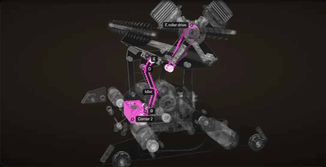
Stage 1: out of the gearbox
A 48-tooth pulley on carrier 2 drives a 12-tooth pulley on B, the passive link's ground pivot: 4:1 up. Both sit on the frame.
Stages 2 and 3: up the passive link
From B to an idler on the passive link, and from the idler to D at its top pin. All three pulleys have 12 teeth, so the speed passes straight through.
Stages 4 and 5: along the coupler
From D to a shaft E on the coupler, still 12 to 12, then from E to the 38-tooth pulley at F, the top of the coupler: 12:38.
F, split to both rollers
The roller drive at F is split to both rollers: the two roller shafts on the arms either side of F, 73 mm out, each with twelve wheels along it.
All five, with the 4-bar moving
The 4-bar swings out to its right endstop on the floor plate while the rollers run. Every belt keeps its shape.
Across to the other side
All the way across to the left endstop, and F keeps turning at 1.26 times carrier 2.
The belts, pulleys and roller shafts are the CAD's, tinted magenta; the moving dots are an overlay on each belt. How F is split to the two roller shafts is not modelled in the CAD, so here both shafts simply turn with F.
Four rows of wheels
The intake has four rows of wheels, and the same PTO drives all four.
- Two rows ride on the 4-bar. Each is a 432 mm shaft, nearly the full length of the robot, with twelve wheels on it, carried on an arm 73 mm out from the arm's pivot at F, the top of the coupler. The roller drive at F is split to both.
- The outermost two rows are not on the 4-bar: they are fixed to the chassis, one along each side of the robot, eight 48 mm wheels each. They are driven by the same PTO that drives the two rows on the 4-bar, through belts on the outermost sides of the robot.
- On each side of the robot a 150 mm tall wall runs the full length, on vertical linear rails at the corners, with an Axon MAX servo and an arm above it.
In the CAD the outer rows' drive leaves the gearbox from carrier 2, the same carrier that drives the belts up to F. A 52-tooth pulley on carrier 2 belts down to a 12-tooth pulley at G, low and to the right of the gearbox, and a 4 mm shaft and a shaft coupler carry that forward on bearings to a 20-tooth pulley just behind the robot's front plate. From there the rows are driven through belts on the robot's outermost sides. Those belts are not in the CAD, so the ratio below is the intended one, picked so the rows run at about 1,500 RPM or a bit more.

Calculation How fast do the outer rows turn?
| Carrier 2, both intake motors the same way | 2,175 RPM | computed in How the PTO is built from the tooth counts and the goBILDA 5000 no-load speed |
|---|---|---|
| Carrier 2 to the 20T pulley at the front | 52T to 12T at G, then a shaft | counted in the CAD |
| Belts to the rows, on the outermost sides | 20T to 120T: 6 : 1 down | intended, for about 1,500+ RPM; not in the CAD |
| Outer row wheels | 48 mm | measured from the CAD |
- 20T pulley: 2,175 × 52/12 = 9,425 RPM.
- With 1 : 1 belts the rows would turn at that same 9,425 RPM, about six times the 1,500 RPM wanted.
- Through the intended 6 : 1: 9,425 / 6 = 1,571 RPM.
- Wheel surface: π × 0.048 m × 1,571 / 60 s = 3.9 m/s, about 1.8 times the drivetrain's 2.21 m/s no-load top speed (below).
Belted down 6 : 1 on the outermost sides, the outer rows run at about 1,570 RPM, and their wheels outrun the robot driving into a ball.
No load, at full speed through the PTO. The belts and their pulleys are not in the CAD: 6 : 1 is the intended ratio, not a modelled one.

One PTO for four rows, a servo for each arm
The 4-bar at transfer, as the CAD holds it. Scroll to run carrier 2, then to turn each arm with its servo.
Four rows of wheels
Two rows ride on arms on top of the 4-bar. The outermost two are fixed to the chassis, one along each side.
One PTO drives all four
Carrier 2 turns. Its belts run up the 4-bar to F, for the rows on the arms. Its side belt runs to G and a shaft to a 20-tooth pulley at the front, which drives the outer rows 6 : 1 down through belts on the outermost sides.
The left arm's servo
Cut just in front of the arms. The servo right of F turns its 14-tooth bevel, which turns the 28-tooth bevel on the left arm: the arm swings about F, half as far as the servo.
The right arm's servo
The servo left of F does the same for the right arm: two servos, two arm angles.
The outer plates, the side walls and everything above the arms are left out, and cut faces are hatched. The belts, pulleys, rows, bevels and arms turn about their axes in the CAD; the dots on the belts are an overlay. The belts from the 20-tooth pulley to the outer rows are not modelled; those rows turn at the intended 6 : 1 from that pulley. The split from F to the rows on the arms is not modelled either, so those rows turn with F.
A servo for each arm
On the 4-bar, the two servos with bevels set the angles of the two arms that hold its rows of wheels. Each arm turns about F with a 28-tooth bevel on it, and each Axon MAX turns a 14-tooth bevel that meshes one of them: the servo right of F turns the left arm, the other the right.
Calculation What does the 2:1 bevel give each arm?
| Axon MAX servo at 4.8 V | 28 kgf·cm stall torque, 0.140 s per 60° | Axon Robotics, MAX MK2 |
|---|---|---|
| Bevel gears | 14T on the servo, 28T on the arm | counted in the CAD |
| Roller shaft from the arm's pivot at F | 73.0 mm | measured from the CAD |
- The arm turns 14/28 = 1/2 as far as its servo, so it gets twice the torque: 2 × 28 = 56 kgf·cm, or 56 × 0.0981 = 5.5 N·m.
- At the roller shaft: 5.5 N·m / 0.073 m = 75 N, about 7.7 kgf.
- The arm turns 30° for each 60° of servo, so 60° of arm takes about 2 × 0.140 = 0.28 s.
Twice the servo's torque at half its speed: about 5.5 N·m at F, or 75 N at the row of wheels.
Datasheet figures at 4.8 V, a REV Control Hub's servo voltage; an estimate, not a test result.
The turret
The shooter sits on a turret toward the back of the robot, its axis 92 mm behind the robot's centre. The ring gear has 158 internal teeth at module 1.5 and is 256 mm across. Four Melonbotics Super Servos stand inside it, so four servos share the work of turning the turret.
The hood and the two flywheel motors ride on top, with our team number, 26115, in a custom number font on both sides.


Turning the turret
The servos, hood, motors and number plates turn together about the ring gear's centre as you scroll; the ring gear, lit orange, stays with the robot.
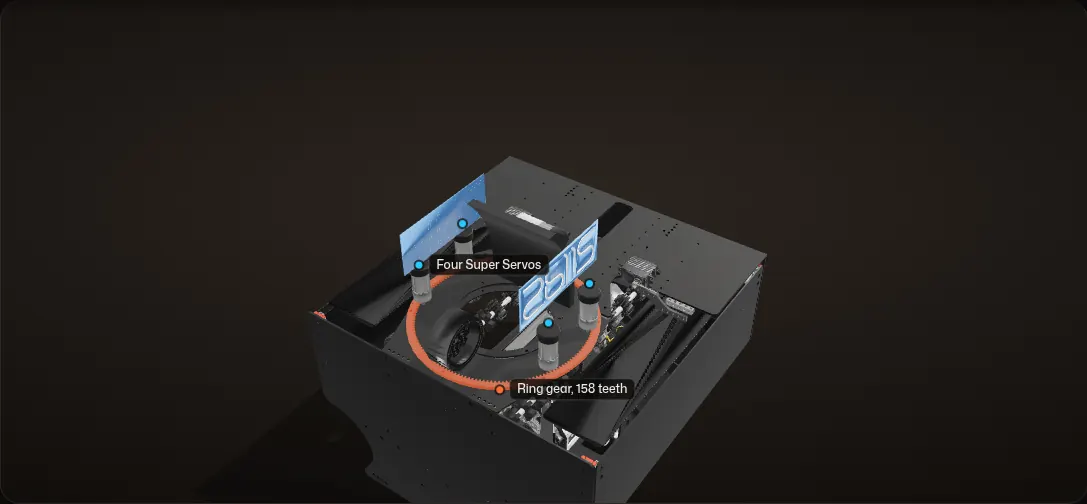
In the CAD the flywheel motors sweep a wider circle than the one the servos stand on, so the servos turn with the turret here. The range is for the animation.
A collinear mecanum drivetrain
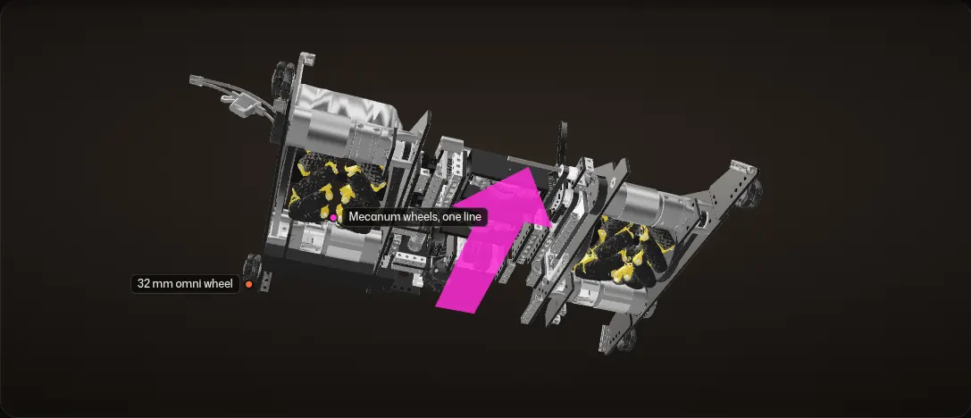
The drivetrain is a collinear mecanum drivetrain, in a narrow column down the middle of the robot between the two intake sides. All four wheels are goBILDA 104 mm mecanum wheels on one line: two pairs, each a left-hand and a right-hand wheel side by side on one axis, 302 mm apart front to back. Each wheel has its own goBILDA 5203 motor (3.7:1, 1,620 RPM) and a 30-to-120-tooth belt, 4:1.

Calculation How fast does it drive?
| Drive motor, no-load speed | 1,620 RPM (3.7:1) | goBILDA 5203-2402-0003 |
|---|---|---|
| Belt | 30T motor pulley to 120T wheel pulley | counted in the CAD |
| Wheel diameter | 104 mm | goBILDA 104 mm mecanum wheel; axle 52 mm above the floor in the CAD |
- Wheel speed: 1,620 × 30/120 = 405 RPM.
- Surface speed: π × 0.104 m × 405 / 60 s = 2.21 m/s.
- 2.21 m/s × 3.281 ft/m = 7.2 ft/s.
About 2.2 m/s (7.2 ft/s) flat out.
A no-load estimate: the real top speed with the robot's weight on the wheels is lower.
The axles run along the robot's length, so driving straight moves the robot toward one of the intake sides, and strafing slides it along its length. In a collinear mecanum drivetrain all four wheels touch the floor on one line, so across the robot there is nothing else to stand on: four 32 mm omni wheels at the corners sit 1.8 mm off the floor in the CAD.

The wheels from underneath
The collinear mecanum drivetrain from below. The two wheels on each axis are a left-hand and a right-hand mecanum wheel, read from their rollers in the CAD, so turning them opposite ways slides the robot along its length.
Drive
All four wheels the same way: the robot moves toward one of the two intake sides.
Strafe
The two wheels on each axle opposite ways: the robot slides along its length.
Turn
Front pair against back pair: the robot turns about its middle.
The wheels and motor pulleys turn about their axes in the CAD as you scroll. The magenta arrow shows which way the robot moves; it is an overlay.
Testing it first
Problem An untested collinear mecanum drivetrain
Would a collinear mecanum drivetrain, all four mecanum wheels on one line, drive straight and turn well?
Fix
Before the drivetrain CAD, we built a quick test chassis out of goBILDA channel with the wheels bunched in the middle, and drove it on foam tiles at home: empty first, then with a bag on top for weight. It drove, and it turned very well.


How the design developed
Feb 28
Drivetrain test
A test chassis for the collinear mecanum drivetrain, the wheels in the middle, driven empty and then loaded.
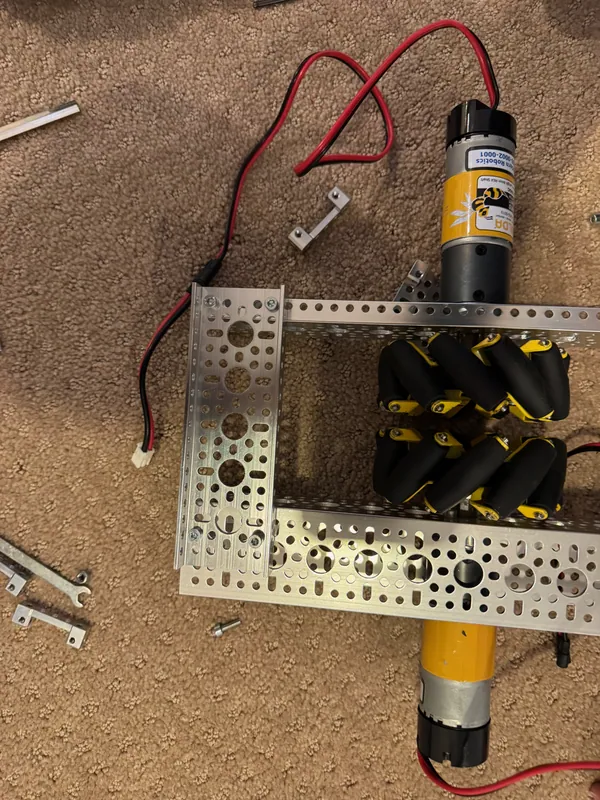
The test chassis frame It turned very well Mar 8
Drive pods
The wheel pairs as two pods on half-round plates, with the intake gearbox as a block between them.
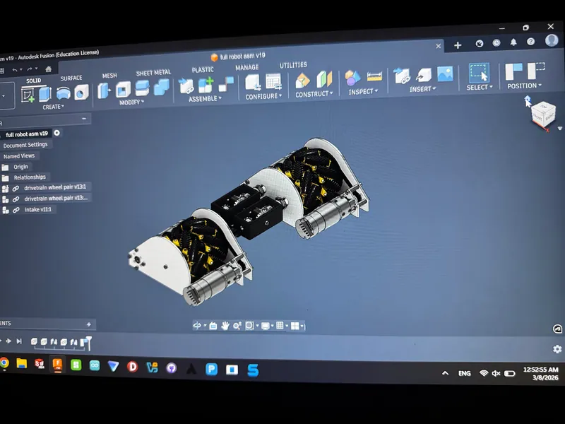
March 8, 2026: two drive pods with the intake gearbox between them 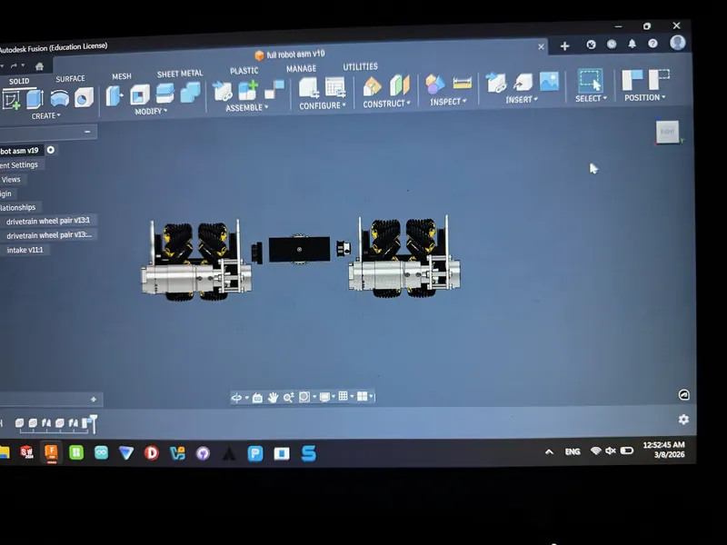
The same layout from the front 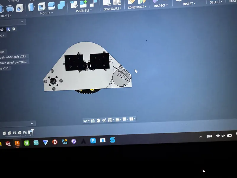
From the side: two black gearbox housings geared together above the pod plate Mar 14
Pod detail and the start of the PTO
The pod with its motor and belt, and the differential gearing starting beside it.
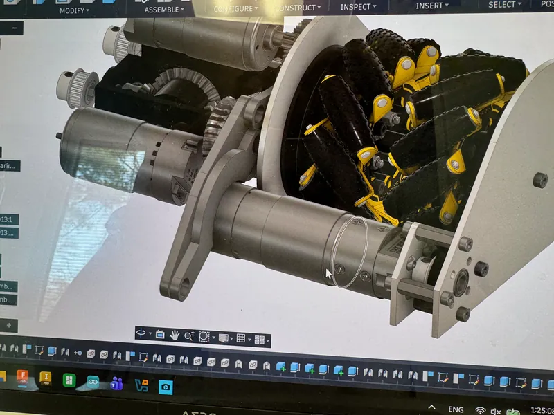
March 14, 2026: a drive pod with its mecanum wheels, motor and belt pulley, and the PTO gearing next to it Mar 16
4-bar, worm and differentials
The carbon fiber links on the worm wheel, and both differentials in place.
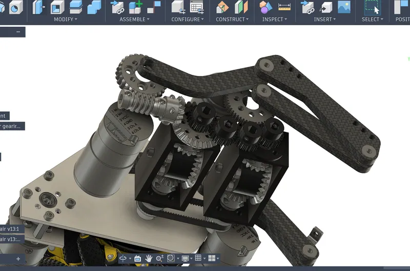
March 16, 2026: the 4-bar on its worm wheel, with the two differentials Orbiting the intake assembly in Fusion 360: both drive pods, the 4-bar links and the differential housings between them Mar 20
The full PTO gearbox
Both intake motors, a differential housing and the spur gears between the carbon fiber plates.
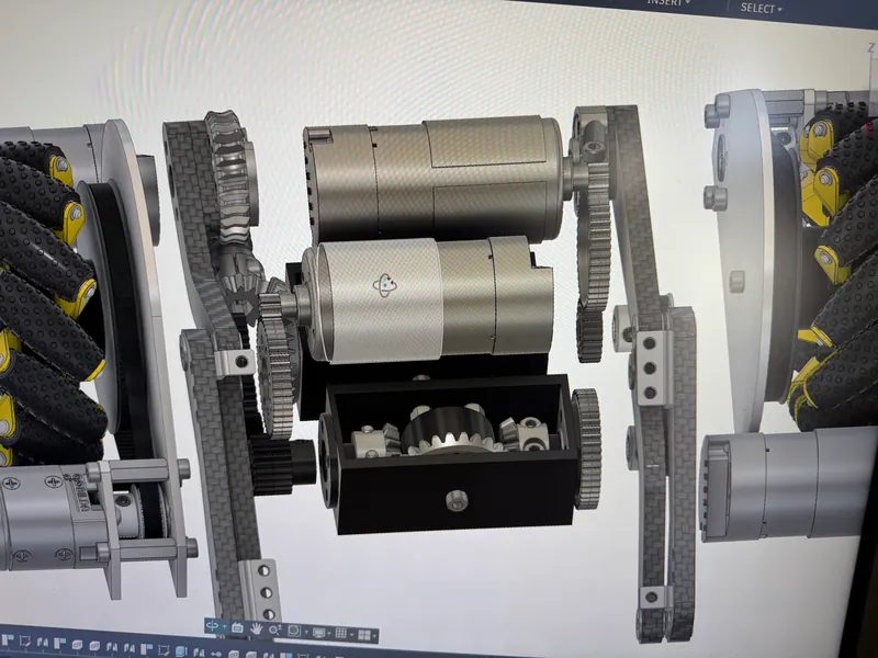
March 20, 2026: the PTO gearbox from above Mar 30
Turret drive
The Super Servos placed on the turret's ring gear.
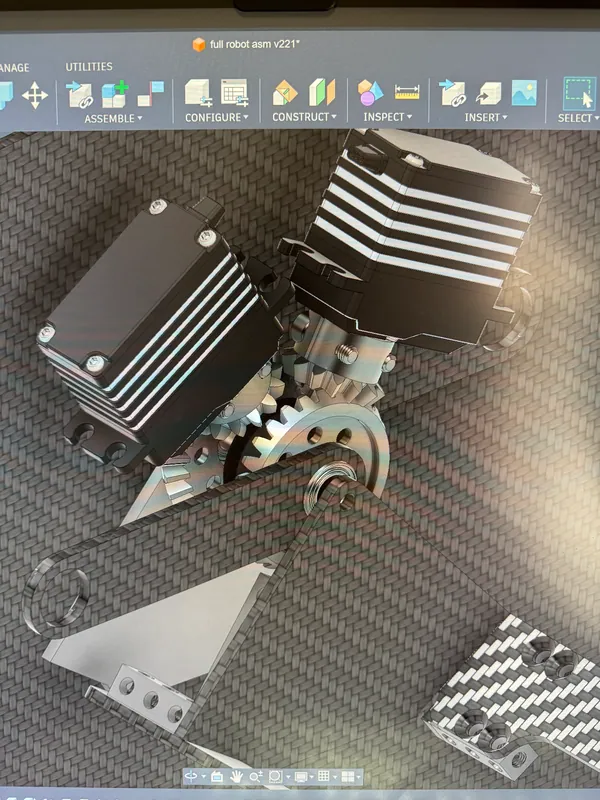
March 30, 2026: Super Servos on the ring gear


Why it was never built
Working out in CAD how to make the differential PTOs work was a useful design exercise: two motors, two differentials, a worm and five belt stages up a moving linkage, packed into an 18 in cube. But the further the design got, the more I could see what building it would take.
Problem Problems I could see coming
I foresaw a lot of construction issues. Everything on this page has to be built, aligned and kept aligned: two bevel differentials tied together by a row of four spur gears and a belt, a worm set, a bevel pair on each arm, belts up the passive link and along the coupler, the side branch to the outer rows, and walls on linear rails, all between carbon fiber plates.
I also foresaw a lot of friction, and a lot of play and slop. Every gear mesh, bearing and belt in a drive takes a little of the power and adds a little play, and in this intake the power to the rows on the 4-bar goes through a gear train, a differential and five belts in a row, so all of it adds up.
Problem Not much to gain
For all that, it would not have offered much meaningful benefit on a real robot.
Problem Out of time
The design never got finished, and the World Championship deadline was coming up.
Fix Improve what already works
So we decided to improve our old robot instead. We doubled its transfer's power, and with it the transfer's speed, and we added a turret: a more reasonable design that built off what we already had. That is the robot we took to Worlds.
