← All projectsFIRST Tech ChallengeSep 2025 to May 2026
FTC DECODE Robot
Team 26115 Alphabots
I designed our first robot, then led a turret shooter for Worlds, where we won the 1st place Sustain Award.
I captained Alphabots, FTC team 26115, through the 2025-26 season, DECODE. I designed our first robot myself: a mecanum chassis, a full-width intake, a ramp that stores three balls and a fixed flywheel shooter.
For the World Championship we kept that chassis and put a turret shooter on top that aims from the robot's odometry pose, so it can shoot from anywhere on the field. The engineering decisions were mine; a student who had never used CAD did the modelling while I guided him through every step. Our team of 11 went from not qualifying for regionals to the 1st place Sustain Award at the FIRST World Championship.
The CAD: what changed from V1 to V2
V1 is the robot I designed and played our first four events with; V2 is the World Championship robot, the same chassis with a turret shooter on top. Here are both, from my CAD files, on one stage. Parts that are identical in both files stay where they are, and only the parts that differ swap, found by comparing the two files body by body.
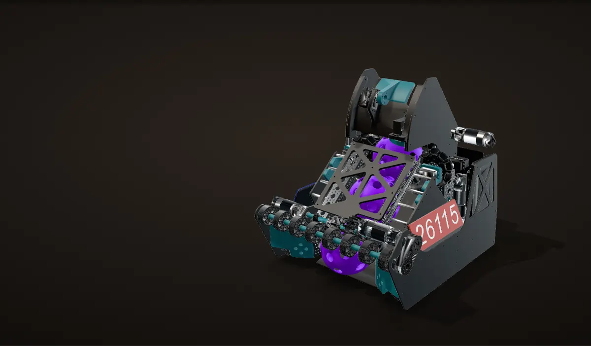
V1, November 2025
The robot I designed: a mecanum chassis, a full-width intake, a ramp that stores three balls and a fixed flywheel shooter at the back.
Cut in half
A section down the middle of the robot shows the ball path. In V1 the top ball waits under a gate in front of a fixed flywheel.
What changed
Tinted: the V1 parts that are not in the Worlds CAD. The shooter, the top of the ramp and some of the plates.
V2, the Worlds robot
The same chassis, intake and ramp, with a turret shooter on top. Its new parts are tinted as they come in.
Cut in half again
In V2 the top ball waits in the bore of the turret bearing, right under the new shooter.
Screws and circuit boards are left out; every other part is the CAD as modelled.
Two robots, one chassis
DECODE is the 2025-26 FIRST Tech Challenge game. Robots pick up purple and green balls, 5 in across (127 mm in the CAD), and shoot them into their alliance's goal. I was the team captain.
We ran two robots on one chassis. I designed V1 myself in the fall of 2025, and it played our four events in January and February 2026. For the World Championship we replaced its fixed shooter with a turret. I made the engineering decisions for the new shooter; a student who had never used CAD before did the modelling, and I guided him through every step.


| V1: the barebones robot | V2: the Worlds robot | |
|---|---|---|
| Designed | Entirely by me, Sep to Nov 2025 | My engineering decisions, modelled by a student I guided, Apr 2026 |
| Drive, intake, ramp | Mecanum drive, 8-wheel intake, 3-ball ramp | The same, plus four TPU spinners along the ramp |
| Shooter | Fixed: two 96 mm wheels on one axle, a motor on each end | On a turret: one 72 mm wheel, two motors through bevel gears |
| Hood | Fixed arc, with a two-position flap on a Swyft servo | A toothed arc, rolled by a servo and a 40-tooth pinion |
| Aiming | Point the back of the robot at the goal | The turret aims from the odometry pose |
| Competed | Four events, Jan to Feb 2026 | FIRST World Championship, Apr 29 to May 2, 2026 |
V1: the robot I designed
Start from the shot
Early in the season I drew the shooter's side view as a dimensioned 2D sketch: the ball, a 96 mm flywheel, the hood arc and a 40° ramp from the intake up to the wheel. That sketch fixed the path a ball takes from the floor to the flywheel, and I built the rest of the robot around it.
The result is one straight path down the middle of the robot. The intake is at the front, three stored balls sit in a line climbing toward the back, and the flywheel is at the back, up top. The shot leaves backward and up, over the rear of the robot.

Chassis
- Four goBILDA 104 mm mecanum wheels, so the robot can strafe and line up without turning.
- Each drive motor turns its wheel through a right-angle bevel pair, so the motors stand up or lie along the sides and the middle of the chassis stays clear for the ramp.
- Carbon fiber side and inner plates with 3D printed brackets.
- Two odometry pods and a goBILDA Pinpoint odometry computer track where the robot is.
- In the CAD it is 15.5 in by 18.0 in in plan and about 18 in tall, inside the 18 in starting cube.


Intake and ramp
The intake is one shaft of eight 48 mm compliant wheels across almost the full width of the robot, driven by one motor through a 36-tooth to 36-tooth belt. Behind it the ramp holds three balls in a line, and a second motor turns compliant wheels inside the ramp that push them up toward the shooter. The first version of the intake stalled; the fix is in Failures and fixes.
Gate, feed wheels and flywheel
The top ball stops under a gate on a Swyft servo. To shoot, the gate swings open and two 96 mm roller wheels on servos, one on each side of the ball, lift it into the flywheel.

The flywheel is two 96 mm wheels side by side on one axle, driven directly from both ends by two goBILDA Yellow Jacket motors, the 1:1, 6,000 rpm version, with no belt or gears in between. The ball is pinched between the wheel and the hood and carried up the front of the wheel. In the CAD the hood's inner surface is 170 mm from the axle, so the 127 mm ball is squeezed about 5 mm against the 96 mm wheel.
Because the shooter is fixed to the chassis, our drivers aimed V1 by pointing the back of the robot at the goal.

A hood with two positions
The end of the hood is a flap on a Swyft servo with two positions: high for the close zone, low for the far zone. Measured around the flywheel axle from the robot's front, the fixed hood ends about 32° up. With the flap down, as modelled, it carries the same arc on to 52°. With the flap up, the arc stops at 32°.
A ball leaves roughly along the tangent where the hood ends. From the CAD that is about 38° above horizontal with the flap down and about 58° with it up: a flatter shot for the far zone and a steeper one for the close zone, from one fixed shooter.
Launch angles on this page are geometry only: the tangent where the hood ends in the CAD, ignoring spin and slip.

A ball through V1
The V1 CAD cut down the middle, with its moving parts rigged about their real axes: the intake shaft, the gate and flap servos, the two feed wheel servos and the flywheel axle. A ball travels the whole path as you scroll.
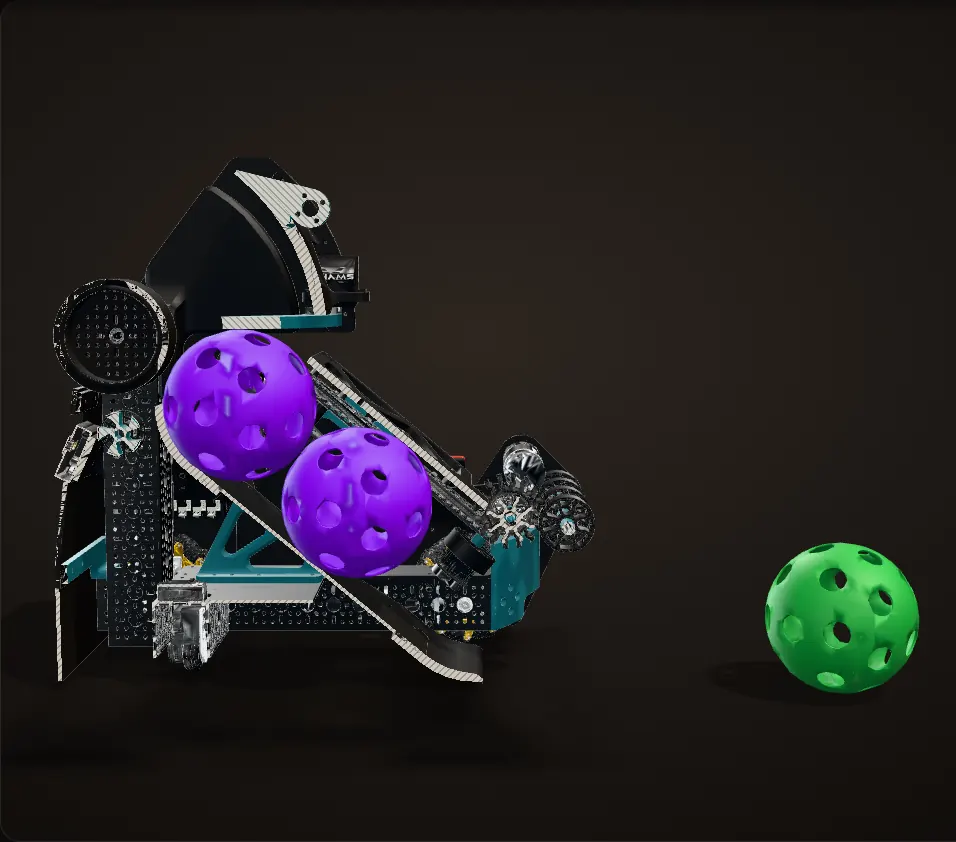
One straight path
The intake is at the front, the ramp climbs toward the back and the flywheel sits at the back, up top. The ramp stores three balls in a line: here two are loaded and a third waits in front of the intake.
The first intake: 1,620 rpm
The intake is one shaft of eight 48 mm compliant wheels, driven by one motor through a 36-tooth to 36-tooth belt. As first built it turned at 1,620 rpm, and on its first test, on November 8, 2025, a ball pushed into the roller row stalled against the spinning wheels (Failures and fixes).
Geared down: 1,150 rpm
I changed the intake gearing to 1,150 rpm: 1.41 times the torque at the roller, for about 29% less speed. A week later the intake swallowed balls and sent them up the ramp.
Flap up: the close zone
With the flap up, the hood stops at 32° around the flywheel axle and the ball leaves about 58° above horizontal. To shoot, the gate swings open and the two 96 mm feed wheels lift the top ball into the flywheel, which carries it up the front of the wheel under the hood. The next two balls move up behind it.
Flap down: the far zone
With the flap down, as modelled, the hood's arc carries on to 52° and the ball leaves about 38° above horizontal: a flatter shot for the far zone, from the same fixed shooter.
The gate and flap turn about their servos' axes in the CAD; how far they swing here is illustrative. The roller turns with the scroll at speeds in the ratio of the two gearings, and the readout gives the real speeds; surface speed uses the 48 mm intake wheels in the CAD. The stall is shown as it was filmed: the ball stops at the roller.
Building V1


V2: a turret for the World Championship
Why a turret
V1 had to point its back at the goal to shoot. For Worlds I wanted a robot that could shoot from anywhere on the field, whichever way it was facing. The World Championship deadline was close, so we kept V1's chassis, intake and ramp and replaced only the shooter.
The engineering decisions on the new shooter were mine. A student on the team who had never used CAD before did the modelling, and I guided him through every step of it.
Turret
- The turret rides on an AndyMark turntable bearing with a 145 mm bore and a 203 mm outside diameter.
- A 150-tooth ring gear on the turret meshes with two 90-tooth gears on the chassis, so each of those gears turns 1.67 times as far as the turret. A Tekin T180 servo, mounted next to the Limelight, rotates the turret.
- The ramp ends under the bearing. The top ball sits in the 145 mm bore and balls feed straight up through the middle of the turret, with 9 mm to spare on each side of a 127 mm ball. Nothing has to reach around the part that turns.
- A Limelight 3A rides on the turret, facing the same way as the shot.

Shooter and hood
- One 72 mm wheel on a cross axle, driven by two 1:1 motors through right-angle bevel gears, so both motors lie along the sides of the turret.
- The hood's outer edge is a toothed arc centred on the flywheel axle, and a servo with a 40-tooth pinion rolls the hood along it. The arc's pitch radius is 180.5 mm and the pinion's 23.6 mm, so the pinion turns 7.65 times as far as the hood.
- Rolling the hood moves the point where the ball leaves the wheel, which sets the launch angle.

Transfer
V2 adds four TPU spinners along the sides of the ramp, on continuous rotation servos, that push the balls up into the turret.

Aiming from the odometry pose
The turret aims from the robot's odometry pose alone. The odometry computer knows where the robot is on the field and which way it faces, so the code works out the direction to the goal, subtracts the robot's heading and turns the turret to that angle.
We planned to fuse the Limelight's AprilTag readings with odometry, but odometry was very good on its own. The Limelight was only there to relocalize the robot after a minute or more, with a button or with a mode that relocalizes on the next AprilTag it sees. In practice we did not use it, because relocalization was not working in time.

The turret, in the Worlds CAD
The V2 CAD with its moving parts rigged about their real axes: the turret on its bearing, the two 90-tooth gears, the hood on its toothed arc and its 40-tooth pinion, the flywheel and the four TPU spinners.
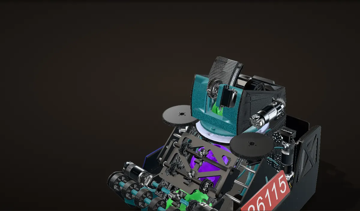
On a turntable bearing
A 145 mm bore, 203 mm outside. A 150-tooth ring gear on the turret meshes with two 90-tooth gears on the chassis.
Turning the turret
Each 90-tooth gear turns 150/90, 1.67 times as far as the turret, the other way. Turned 60° here, the turret turns each gear 100°.
Rolling the hood
A servo with a 40-tooth pinion rolls the hood along its toothed arc, centred on the flywheel axle. The arc's pitch radius is 180.5 mm and the pinion's 23.6 mm, so the pinion turns 7.65 times as far as the hood, the other way: rolled 20° here, the hood turns it 153°.
Feeding a ball
The four TPU spinners along the sides of the ramp push the balls up. The top ball waits in the bearing's bore, with 9 mm to spare on each side, and feeds straight up onto the 72 mm flywheel, under the hood and out. Nothing has to reach around the part that turns.
Tooth counts and pitch radii from the CAD. How far the turret turns here is illustrative, not the robot's real travel limit; the hood rolls only where the pinion stays on the arc in the CAD. Launch angles are geometry only.
The code
Our robot code is Java on the FTC SDK. The repository is private, so there is no link here, but this is how it is put together.
- Localization. A goBILDA Pinpoint odometry computer reads the two odometry pods and keeps the robot's pose: x, y and heading on the field.
- Autonomous. Pedro Pathing follows chains of Bezier lines and curves, and a numbered state machine steps through the routine: drive to the launch zone and fire the three preloaded balls, drive through a row of three with the intake running, go back and shoot, and repeat for the next row. To fire, it opens the gate and runs the feed wheels for about a second.
- Flywheel. A PIDF loop on the average speed of the two motors' encoders, with a feedforward term proportional to the target speed. The output is multiplied by 13 V over the measured battery voltage, so the wheel gets the same drive as the battery sags, and the voltage is only read every half second to keep the loop fast. The driver switches between two speed presets with the bumpers.
- Turret (V2). It aims from the odometry pose, as above. A centering routine on the Driver Hub sets the servo position for a centered turret.
Calculation What do the two flywheel presets mean at the ball?
| V1 flywheel | 96 mm, driven directly by two 6,000 rpm motors | measured from the CAD; goBILDA 6,000 rpm Yellow Jacket |
|---|---|---|
| Presets | 2,300 and 4,000 rpm | our Driver Hub readout |
- Wheel surface speed: π × 0.096 m × 2,300 / 60 = 11.6 m/s, and π × 0.096 m × 4,000 / 60 = 20.1 m/s
- The ball rolls between the moving wheel and the still hood, so with no slip its centre moves at half the surface speed: about 5.8 and 10 m/s
- Headroom: 4,000 rpm is 4,000 / 6,000 = 67 % of the motors' free speed, 2,300 rpm is 38 %
The presets launch a ball at roughly 6 and 10 m/s, and even the high one leaves the motors a third of their free speed to pull the wheel back up to speed after each shot.
Estimate: no slip and no squeeze losses, so real launch speeds are lower.

How the season went
Sep 2025
The shot first
I drew the ball path in 2D before modelling anything else, then built all of V1's CAD around it.
Nov 2025
V1 built
The carbon fiber side plates went together in early November. The intake stalled on its first test on November 8; a week later, geared down, it took in two balls at once. By late November V1 was shooting into the goal.
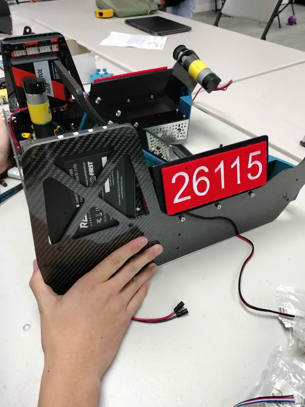
November 7: a carbon fiber side plate with its drive motor and number plate, before it went on the robot Dec 2025 to Jan 2026
Autonomous and consistent shots
Full autonomous routines on our practice field, and a long chase for consistent shots: first the shooter's stiffness, then the flywheel's inertia.
Jan to Feb 2026
Four events with V1
The Moorefield, WV and Laurel, MD qualifiers and the Chesapeake Championship: Inspire Award 2nd and 3rd place and a Reach Award.
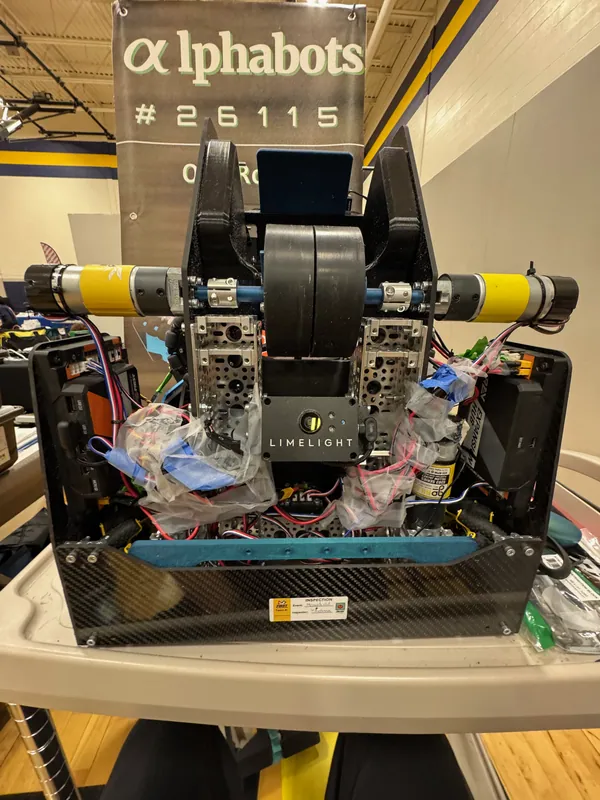
V1 on event day at the Moorefield, WV Qualifier II, January 11, 2026 Apr 2026
V2: the turret
The new turret shooter went onto the same chassis in April. By April 18 the turret was tracking the goal on our practice field (the second video at the top of this page), and on April 27 a test showed its range was off.
The turret before it was mounted: the turntable bearing, the printed turret body and the flywheel shroud Apr 29 to May 2, 2026
The World Championship
Jackson Division. A printed servo mount broke and I reprinted it overnight. The team won the 1st place Sustain Award.
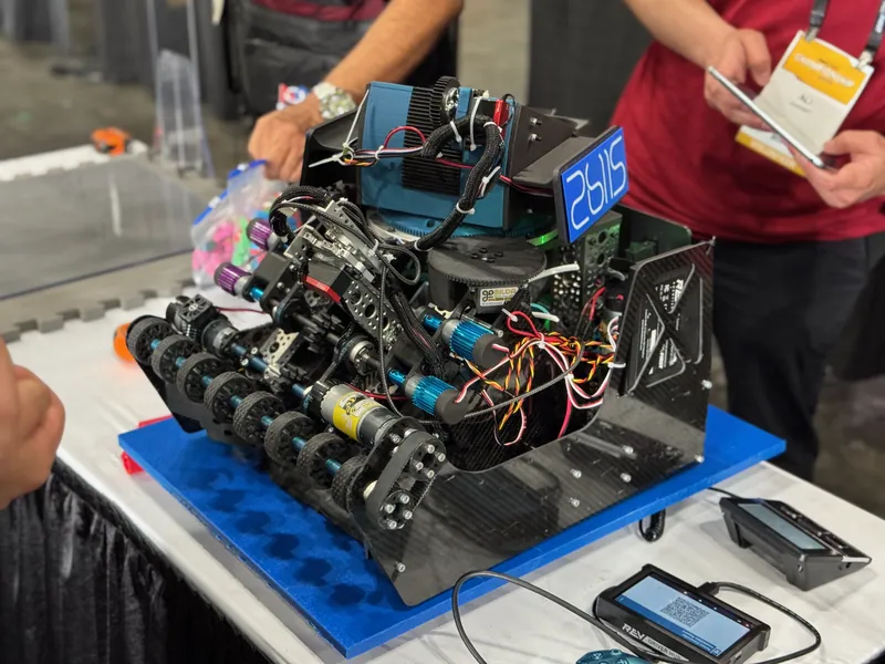
V2 at inspection at the World Championship


Failures and fixes
An intake that would not take a ball
Problem Intake stall
On the first intake test, on November 8, 2025, a ball pushed into the roller row stalled against the spinning wheels and did not come in.
Fix
I changed the intake gearing from 1,620 rpm to 1,150 rpm. A week later, on November 15, the intake swallowed two balls side by side and sent them up the ramp.
Calculation What did gearing down cost?
| Intake speed, before and after | 1,620 rpm, then 1,150 rpm | the gearing I changed |
|---|---|---|
| Intake wheels | 48 mm, on the intake shaft through a 36 to 36 tooth belt | measured from the CAD |
| Drive motors and wheels | 435 rpm through 1 : 1 miter gears to 104 mm mecanum wheels | goBILDA 435 rpm Yellow Jacket, goBILDA miter gears, CAD |
- Torque at the roller: 1,620 / 1,150 = 1.41 times as much, for 29 % less speed
- Roller surface speed: π × 0.048 m × 1,620 / 60 = 4.1 m/s before, π × 0.048 m × 1,150 / 60 = 2.9 m/s after
- Chassis top speed, driving straight: π × 0.104 m × 435 / 60 = 2.4 m/s
Geared down, the roller has 41 % more torque and its surface still runs about 1.2 times the chassis's top speed (it was 1.7 times): it still outruns the robot driving into a ball.
Free speeds from the datasheets, no load; a loaded motor runs slower.
Inconsistent shots
Problem Shot consistency
Our shots were not consistent. In December you can hear it in our test videos ("the flywheel lost its RPM"), and the Driver Hub readout shows the wheel speed swinging around its target while we fire.
We traced it to two things. The first was the stiffness of the shooter assembly. The second showed up once the shooter was stiff: balls still left differently from shot to shot, and that came down to the flywheel's inertia.
Fix
We stiffened the shooter assembly.
For inertia, we first packed the flywheel hub with steel nuts. That helped somewhat. Real steel flywheels helped much more and made our shots much more consistent.
Why inertia matters: every ball takes energy out of the spinning wheel, whose energy is ½Iω². The bigger the moment of inertia I, the smaller the drop in speed for the same energy, so the next ball leaves at closer to the same speed.

A turret test with the range off
Problem Tracking range
On April 27 we turned the robot on the floor with the tracker running (the video here). The turret tried to stay on target, but its range was off: the servo covered much more angle than the code expected.
Calibration
That night the code got a centering routine on the Driver Hub: turn the turret until it is physically centered, note the servo position, and write it into the tracker code as the center.
A servo mount at the World Championship
Problem Broken servo mount
At the World Championship a printed servo mount on the new shooter broke.
I had told the student to add another attachment point, which made the mount stiffer. When we adjusted the gears they still skipped at times, so we pushed down on the mount to keep them in mesh. The mount was missing a fillet, which left an extremely sharp inside corner. A sharp corner concentrates stress, and it broke right there.
Fix
I reprinted the mount overnight.


Aiming from the pose
The Worlds robot on a field, driving a scripted path. Like the real turret, it aims from the robot's pose alone: where the robot is and which way it points. The magenta arc is the ball's path.
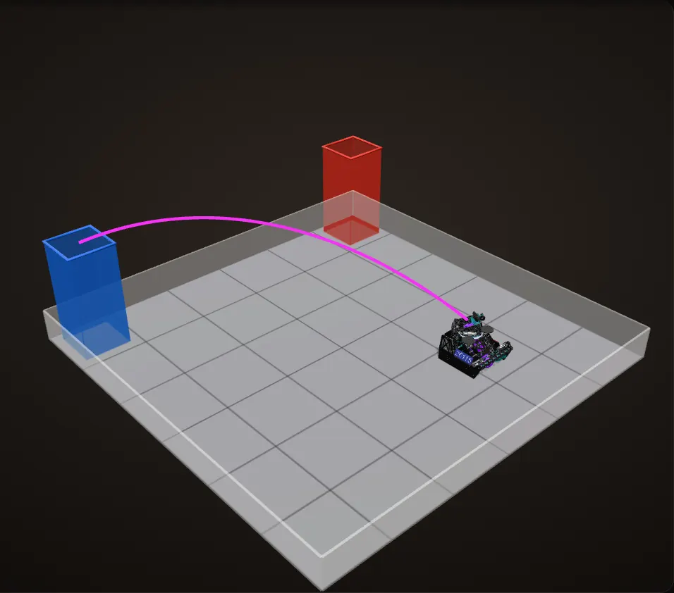
The pose
The odometry computer knows where the robot is on the field and which way it faces. From that pose the code works out the direction to the goal, subtracts the robot's heading and turns the turret to that angle.
Drive and turn
The chassis drives across the field and turns a quarter turn. The turret turns the other way as it goes, so the shooter stays on the goal whichever way the robot faces.
Shoot from here
Stopped, the robot fires along the magenta arc: a plain projectile from the hood to the goal at the hood's modelled launch angle.
Strafe to the far side
Mecanum wheels let the chassis slide sideways and turn at the same time. The turret angle comes from the pose alone the whole way.
From farther away
Farther from the goal, the same launch angle needs a faster ball: the readout gives the speed a plain projectile would need from each spot.
Only the robot is CAD. The field, walls and goals are simplified stand-ins and the path is scripted. The arc is a plain projectile with no drag or spin, leaving the hood at its modelled 40° launch angle, and the turret's real travel limit is not modelled.
Results
| Event | Dates | Robot | Result |
|---|---|---|---|
| Moorefield, WV Qualifier II | Jan 11, 2026 | V1 | Rank 14 of 34; 3-1-1; playoffs 1-2 |
| Laurel, MD Qualifier I | Jan 31, 2026 | V1 | Rank 13 of 35; 3-0-2; Inspire Award 2nd Place |
| Laurel, MD Qualifier 2 | Feb 1, 2026 | V1 | Rank 6 of 28; 5-0 in qualifications; playoffs 3-2; Inspire Award 3rd Place |
| Chesapeake Championship, Blue Crab Division | Feb 6 to 8, 2026 | V1 | Rank 15 of 48; 5-0-2; playoffs 1-2; Reach Award |
| FIRST World Championship, Jackson Division | Apr 29 to May 2, 2026 | V2 | Sustain Award, 1st place |
One of the most efficient shooters all day.
The event caster, on V1 in playoff match 4 at the Moorefield, WV Qualifier II

What I would change
V2 is the robot we finished the season with, so this is about V2.
Next time Gear flanges
Add flanges to the gears so they cannot skip. At Worlds we were pushing down on a printed mount to keep them in mesh, and that is where it broke.
Next time Own the software earlier
Take on the software myself sooner. The turret code had a problem that went unfound for weeks.