← All projectsFIRST Robotics CompetitionJan to Mar 2026

FRC REBUILT Robot

Team 2856 Planetary Drive

Designed solo and remotely in my first FRC season: three independent shooters on a swerve drive, 22.0 in tall to drive under the trench. It played in the playoffs at the Smoky Mountains Regional.

SoloRobot design, done remotely
3Independent shooters
21 of 46Qualification rank
Round 2Playoffs, 7th alliance
The robot at the 2026 Smoky Mountains Regional, with fuel in the hopper
My CAD of it, as of Feb 18. Nothing changed after this model.

I designed this robot on my own for FRC team 2856, Planetary Drive, from Paul Laurence Dunbar High School in Lexington, Kentucky. I had a friend on the team, and the team had never used CAD. It was my first FRC season, and I worked on it remotely from Maryland.

It has a pivoting roller intake that carries the front of the hopper with it, three independent shooters and a swerve drive, and it stands 22.0 in tall so it drives under the trench. I planned small test iterations sized to the time the team had, and the design did not change after Feb 18. At the 2026 Smoky Mountains Regional we ranked 21st of 46, were picked onto the 7th alliance and went out in the second round of the playoffs.

The robot, driven by your scroll

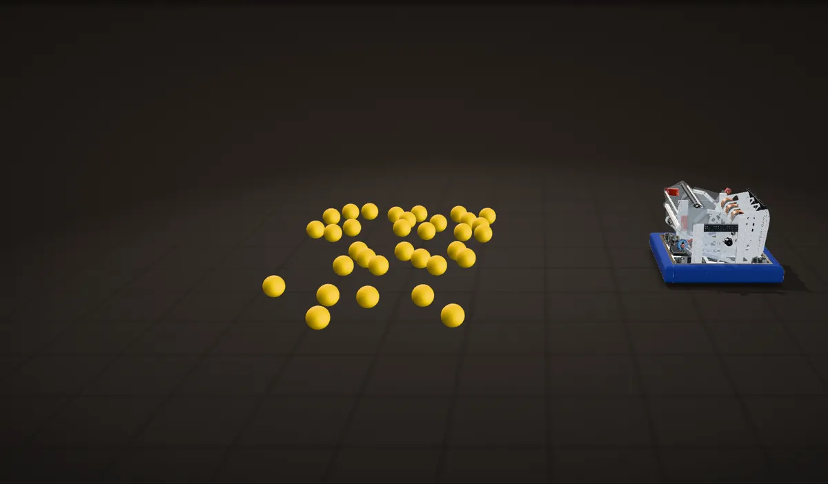
This is my real CAD of the competition robot. Scroll and it starts a match folded up, drives to the fuel, drops its intake, picks the fuel up and runs it through the transfer and the three shooters. Only the fuel, the floor and the labels are drawn in.

  1. Start of a match

    REBUILT is played with 5.91 in foam balls called fuel. The fuel is on the left. The robot starts folded up: the intake arm is swung back until all of it is inside the inner edge of the wooden bumper frame, which is what makes the starting position legal.

  2. Swerve drive

    Four REV MAXSwerve modules, one in each corner of a 26.5 in square frame. Each wheel steers on its own, so the robot can drive any direction without turning first. We used MAXSwerve because the team already had the modules.

  3. Intake pivot

    A NEO on a 25:1 MAXPlanetary turns a 12 tooth sprocket, and #25 chain runs up to a 40 tooth sprocket on the arm: 83.3:1 in total, counted from the CAD. The arm swings 132 degrees down to intake. The front of the hopper rides on the arm, and its sprung top panel unfolds on the way.

  4. Intake

    A full-width roller pulls the fuel in. The NEO 2.0 that spins it sits on the frame and drives it through two belts: 12 to 24 teeth up to a pulley on the pivot axis, then 24 to 24 teeth out to the roller. The side plates are cut away here so both belts show.

  5. Into the hopper, toward the hub

    The fuel collects in the hopper. Its floor peaks at the intake pivot and slopes down toward the back, and two divider plates split it into three lanes, one per shooter.

  6. Transfer

    A section through the middle lane. At the bottom of each lane two stacked sets of 1.625 in flex wheels lift the fuel up a curved polycarbonate backing. Each set is on one 1/2 in hex shaft across the whole robot, a belt ties the two shafts 1:1, and a NEO 2.0 sits at each end.

  7. Three shooters

    Each lane ends in its own shooter: a Kraken X60 and two 4 in wheels that squeeze the fuel against a 3D printed hood. The hood curls forward at the top, so the fuel leaves up and forward, over the robot. The arcs are drawn, not measured.

  8. 22 inches

    The opening under each trench is 22.25 in. The robot is 22.0 in tall in the CAD, so it drives under the trench, and it did.

Designing a robot from another state

Planetary Drive had never used CAD. I had a friend on the team, so I designed the whole robot for them in Fusion 360, in my first FRC season. WestCoast Products’ open 2026 robot was my initial inspiration, and what the two have in common is three separate shooters.

Problem Remote, with a team new to CAD

I was in Maryland for the whole season and the team was in Kentucky. I could never stand next to the robot, and the team had never used CAD.

Fix

I shared the model through Fusion 360 links, so anyone on the team could open it, and sent DXF files for the flat parts. Bill, a machinist in the shop, waterjet cut all of the aluminum plates from them. Some of the build happened over video calls, like the one pictured here.

Mar 10, a screenshot from a video call with the shop: the intake pivot sprocket and its chain going on beside an upright

Problem No shared schedule

The team was not very competitive, and syncing a timeline for design iterations was hard.

Fix

I asked how much time the team had and planned small test iterations that fit it. The design settled through those iterations: nothing changed between the Feb 18 model and the final CAD.

Feb 13: a shooter side plate waterjet cut from my DXF, with the triangle pockets and PLANETARY DRIVE cut through

The CAD, mechanism by mechanism

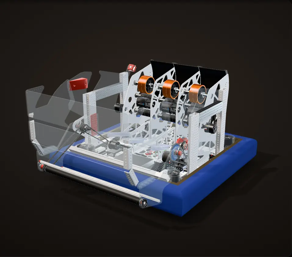
The final robot, from my Fusion 360 model with the fasteners left out. Nothing changed between the Feb 18 model and this final CAD.

  1. The whole robot

    The intake is at the front, the shooters are at the back, and everything between them is hopper.

  2. Drive

    Four REV MAXSwerve modules, lit, one in each corner of the 26.5 in square frame, with the bumpers drawn see-through. The robot is 33.0 in square over the bumpers.

  3. Intake

    The full-width roller on its arm at the front, and the two belts that spin it from a NEO 2.0 on the frame, 2:1 overall.

  4. Transfer

    A section through the middle lane. Two full-width shafts of flex wheels at the back of the hopper lift the fuel into the shooters, tied 1:1 by a belt.

  5. Shooters

    Three shooters side by side, one per lane, each a Kraken X60 and two 4 in wheels under a 3D printed hood.

  6. Three lanes

    The section sweeps across the robot. Two divider plates split the hopper into three lanes, one per shooter, each 6.5 in wide between the shooter plates for 5.91 in fuel.

Polycarbonate is drawn clear, as on the real robot. Spin directions follow the fuel path; speeds are not to scale.

The big decisions

Four choices shaped the rest of the robot.

Three independent shooters, no turret

Problem What shooter

The shooter had to be something this team could build and keep running.

Fix

Three independent shooters, one per lane. I thought three separate shooters would be more reliable than one big full-width shooter, a single set of wheels across the whole robot. The team was not experienced, so a turret was out.

Next time

In hindsight the strongest teams used the full-width shooter, and we did not have time to test enough to find that out ourselves. Next time I would take out the separators between the shooters, because they cause jams, and run one big bar all the way across.

The finished robot at the regional, orange flywheels at the back and the hopper full of fuel

22.0 inches tall

The opening under each trench on the REBUILT field is 22.25 in. I kept the whole robot to 22.0 in so it could drive under the trench, and it did.

MAXSwerve

Four REV MAXSwerve modules with 3 in wheels and the medium speed gearing, each with a NEO to drive and a NEO 550 to steer. We used them because the team had them.

No climber

The robot has no climber for the tower. We ran out of time.

Feb 7: the four swerve modules wired up on a wooden test frame

Frame and drivetrain

The frame is 26.5 in square in 2x1 in pre-drilled aluminum box tube: 19.5 in rails between the four MAXSwerve modules, joined by gussets, with a triangle-pocketed aluminum belly pan. The roboRIO, the power distribution panel and the battery sit on the pan. Over the bumpers the robot is 33.0 in square, and the wheelbase is 23.0 in.

The modules were wired up on a wooden test frame first. The aluminum frame and pan show up in the build photos a week later.

Feb 13: the aluminum frame and the triangle-pocketed belly pan with the modules in

The intake and its pivot

The roller is a 22.6 in polycarbonate tube with a silicone sleeve, on a 1/2 in hex live axle. It sits at the end of an arm made of two 3/8 in polycarbonate plates, 12.0 in from the pivot.

Problem Driving a roller on a moving arm

The roller rides on a swinging arm, and it has to keep spinning at every arm angle.

Fix

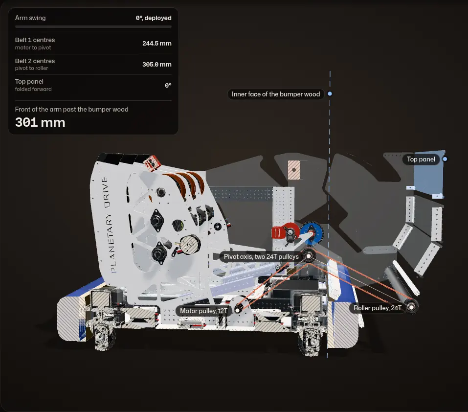
The NEO 2.0 that spins the roller sits on the frame. Its belt climbs 12 to 24 teeth to a pulley on the pivot axis, and a second belt runs 24 to 24 teeth from that axis out to the roller, 2:1 overall. With the middle pulley on the pivot axis, both belts keep fixed centres wherever the arm is: 244.5 mm between the pulley centres in the CAD for the first (motor and pivot are both on the frame) and 305.0 mm for the second (pivot and roller are both on the arm).

Calculation How fast does the roller surface move?

NEO 2.0 free speed5,676 rpmREV NEO 2.0
Belts, motor to roller12 to 24, then 24 to 24 teeth: 2 : 1counted from the CAD
Roller diameter over the silicone sleeve34.8 mmmeasured from the CAD
  1. Roller speed: 5,676 / 2 = 2,838 rpm
  2. Surface speed: π × 0.0348 m × 2,838 / 60 s = 5.2 m/s (17 ft/s)

Even geared down 2 : 1, the roller surface moves at up to about 5.2 m/s where it grabs the fuel.

Free speed, no load: the roller slows when it is pulling fuel in.

The arm is driven on the other side. A NEO on a 25:1 MAXPlanetary turns a 12 tooth sprocket, and #25 chain runs to a 40 tooth sprocket bolted to the arm, 83.3:1 in total. A REV Through Bore Encoder sits on a 24 tooth sprocket that rides on the same chain, so it turns 40/24 = 1.67 times as far as the arm. Tooth counts are from the CAD.

The same two-belt roller drive in my first model (Jan 31): a NEO, a belt up to a shared pulley, and a second belt down to the roller

Calculation What does 83.3 : 1 give the arm?

NEO free speed and stall torque5,676 rpm, 2.6 N·mREV NEO
Reduction, motor to arm25 × 40 / 12 = 83.3 : 1MAXPlanetary 25:1, sprockets counted from the CAD
Stow swing132°computed from the CAD
  1. Arm speed at free speed: 5,676 / 83.3 = 68 rpm = 409° per second
  2. The whole 132° swing: 132 / 409 = 0.32 s
  3. Stall torque at the arm: 2.6 N·m × 83.3 = 217 N·m

At best the arm swings from stowed to deployed in about a third of a second, and at stall the pivot can push with about 217 N·m.

Upper bounds: no gearbox or chain losses, no time to speed up or slow down, and REV’s measured NEO numbers.

Calculation How finely does the encoder see the arm?

Through Bore Encoder8,192 counts per turn (quadrature); 10-bit absolute outputREV Through Bore Encoder
Encoder turns per arm turn40 / 24 = 1.67counted from the CAD
Pivot to roller12.0 in (305 mm)measured from the CAD
  1. Counts per arm turn: 8,192 × 1.67 = 13,653, so one count is 360° / 13,653 = 0.026°
  2. At the roller: 305 mm × 0.026° × π / 180 = 0.14 mm per count
  3. The 132° stow swing is 132 × 1.67 = 220° at the encoder, less than one turn

One count is about a seventh of a millimetre at the roller, and because the whole swing is less than one encoder turn, its absolute reading can be zeroed so it never wraps around between stowed and deployed.

Resolution only; chain slack between the arm and the encoder sprocket is not counted.

The first model’s large sprocket and chain beside a pre-drilled upright

Stowed for the start, deployed to play

A side view from the roller motor side, with the parts outside the belts cut away. The readout is measured on the CAD as the arm swings.

  1. Deployed

    Deployed, the front of the intake and hopper reaches 8.6 in past the front bumper in the CAD. To start a match legally all of it has to fold back inside the robot, until it is completely inside the inner edge of the wooden bumper frame: the dashed line.

  2. Swinging up, belts unchanged

    The pivot swings the arm up and back. The roller keeps turning the whole way, because the middle pulley sits on the pivot axis: both belts keep fixed centres. Watch the readout: the distances between the pulley centres do not change.

  3. The top panel folds

    The front of the hopper, its side panels and front panels, is bolted to the arm and swings with it, so the hopper is bigger whenever the intake is down. Its top panel pivots on a single bolt at each lower corner. A spring runs from the one hole at its top corner to a row of holes along the top of the side panel, which sets the tension, so the panel starts the match folded inward and unfolds.

    In the CAD it has to fold from about 106 degrees of swing on to stay clear of the shooters and the transfer, and stowed it is folded about 100 degrees.

  4. Stowed

    In the CAD the whole arm is inside the inner edge of the bumper wood after a 132 degree swing, which is 220 degrees at the encoder: still less than one turn.

The arm turns about its real pivot axis from the CAD, and the dashed line is the inner face of the bumper wood. The belt centres are measured between the pulley centres at every angle; the distance past the bumper wood is measured on the CAD for every degree of swing.

Hopper and transfer

The hopper walls are 0.177 in polycarbonate. Its floor peaks at the intake pivot and slopes down toward the back, so the fuel rolls to the shooters on its own, and two divider plates split it into three lanes. Each lane is 6.5 in wide for 5.91 in fuel, measured between the shooter plates in the CAD.

At the back of each lane the fuel meets two stacked sets of 1.625 in, 60A flex wheels, four low and three high. They push it up a bent polycarbonate backing that curves from the floor up into the shooter. The lower and upper sets each sit on one 1/2 in hex shaft that runs the full width of the robot; an HTD belt on 92 mm centres links them 1:1, and a NEO 2.0 sits at each end.

Next time

Put the hopper on a linear system, so it can retract and force the fuel through the shooters.

Early March: a Kraken X60 next to the flex-wheel transfer rollers on the real robot
Mar 7: the assembled robot from the back, three lanes with the bent backing and the flex wheels across all three

Three shooters

Three shooters sit side by side, one per lane. Each is a Kraken X60 and a short 1/2 in hex shaft carrying two 4 in wheels, with a 3D printed hood behind them. In the CAD the hood sits 133 mm from the wheels, so each 150 mm ball is squeezed by about 17 mm as it goes through. The hood curls forward at the top, so the fuel leaves up and forward over the robot.

The shooter side plates are aluminum with triangular pockets and the team name cut through them. The Feb 11 model still had solid plates with a few holes; by Feb 13 the cut plates had the pockets and the lettering.

Feb 11: the three shooter bays in the model, each with its own motor, between solid side plates

By the numbers

Measured from my final Fusion 360 model or read from its part names. The stow swing and the squeeze are computed from the model.
In the CAD
Frame26.5 in square, 33.0 in over the bumpers
Wheelbase23.0 in square
Height22.0 in (trench opening 22.25 in)
Intake roller22.6 in long, NEO 2.0, 2:1 through two HTD belts
Intake arm12.0 in pivot to roller, 3/8 in polycarbonate
Intake pivotNEO, 25:1 MAXPlanetary, 12 to 40 tooth #25 chain: 83.3:1
Stow swing132 degrees, until the whole arm is inside the bumper wood
Pivot encoderREV Through Bore Encoder on a 24 tooth chain sprocket, 1.67 turns per arm turn
Lanes3, each 6.5 in wide
Transfer21 flex wheels, 1.625 in, on two full-width shafts, two NEO 2.0s
Shooters3, each a Kraken X60 and two 4 in wheels, 17 mm squeeze on the fuel
Motors15: 8 in the swerve modules, 3 Kraken X60, 3 NEO 2.0, 1 NEO
CameraArducam on a 3D printed mount at the top rear

How the design changed

  1. Jan 31

    First model

    Swerve drive, the intake arm, a clear hopper wall at the front and two tall uprights. No shooter yet. The two-belt roller drive is already there.

    The first model: swerve corners, the intake arm and a clear front hopper wall
    The first model: swerve corners, the intake arm and a clear front hopper wall
  2. Feb 4

    Fuel path

    The fuel path sketched over a side view of the model in the Fusion viewer: up off the floor at the front and into the robot.

    The fuel path marked up over a side view of the model
    The fuel path marked up over a side view of the model
  3. Feb 7

    Drivetrain on wood

    The four swerve modules wired up on a wooden test frame.

    Swerve modules on the wooden test frame
    Swerve modules on the wooden test frame
  4. Feb 11

    Three shooters

    Three shooter bays with orange wheels and a motor under each, between solid side plates with a few holes.

    Three shooter bays in the model, solid side plates
    Three shooter bays in the model, solid side plates
  5. Feb 13

    First cut parts

    The shooter side plates are now pocketed with triangles and carry the team name, and the pocketed belly pan is cut. Bill waterjet cut the aluminum plates from my DXFs.

    A cut shooter side plate
    A cut shooter side plate
    The frame and belly pan with the modules in
    The frame and belly pan with the modules in
  6. Feb 18

    Final design

    Pocketed shooter plates in the model and a frame over the shooters. Nothing changed between this model and the final CAD.

    The Feb 18 model
    The Feb 18 model
  7. Mar 5 to 10

    Built

    The robot assembled from the model, wiring in progress. On Mar 10 the intake pivot sprocket went on while I was on a video call with the shop.

    The assembled robot from the back
    The assembled robot from the back
    The intake pivot sprocket going on, seen over a video call
    The intake pivot sprocket going on, seen over a video call
  8. Mar 19

    Competition

    At the Smoky Mountains Regional: 21st of 46 in qualifications, then picked onto the 7th alliance.

    The robot at the regional, with the team behind it
    The robot at the regional, with the team behind it

At the Smoky Mountains Regional

We ranked 21st of 46 in qualifications and were picked onto the 7th alliance. We went out in the second round of the playoffs, in a lower bracket match the 6th alliance won 134 to 110.

Autonomous in that match, from the event broadcast. We were Alliance 7, in red.