← All projectsMIT Beaver Works Summer InstituteJul 2025
Drone Grabber Arm
A robotic arm under a drone for grabbing household objects, for example in senior homes.


An arm that hangs under a quadcopter and grabs things, like a bottle of water off a table. The idea was a drone that could fetch household items in a place like a senior home, because a drone is more flexible than a ground robot.
I designed it in CAD and built the whole arm as part of the MIT Beaver Works Summer Institute: two servo joints driving the links directly, links made from spare carbon fiber drone arms, and a 3D-printed claw. It was almost ready to go on the drone when we pivoted, and the same team went on to build the Hybrid Detachable UAV-UGV.
The idea
That summer at the MIT Beaver Works Summer Institute, our main objective was software only, and I wanted to do an additional hardware project with my team. I already had the idea of an arm on a drone that could grab things. My teammates took it further: a drone that could work in a place like a senior home and fetch household items, because a drone is more flexible than a ground robot.
Problem Safety
A drone with spinning propellers flying around people is an obvious safety concern.
Answer
Drones with propeller guards already exist, so it could be made safe. And the idea is not limited to senior homes: a drone that can carry household items generalizes to other jobs.
How it would pick up a bottle
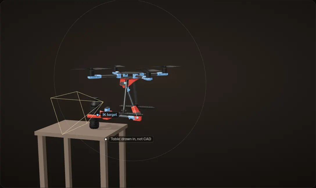
This is the plan for a grab, animated on the real CAD. None of it ran: we pivoted before the arm went on the drone.
1. Find the bottle
The drone flies in with the arm raised. A camera on the end of the arm finds the bottle and works out where it is relative to the drone.
2. Close in and hold position
The drone flies closer and holds its position.
3. Reach it with inverse kinematics
The claw opens, and the arm uses inverse kinematics to move it to the bottle: the IK target in orange, the two links in blue.
4. Close the claw
The claw closes around the bottle. One servo turns both jaws, geared to each other at their pivots.
5. Lift off with it
The drone lifts off with it, and the arm folds back to its pose in the CAD, holding the bottle under the middle of the drone.
The plan, animated: none of it ran, because we pivoted before the arm went on the drone. The table, the camera, its view and the detection box are drawn in; they are not in the CAD. The hover point, the path and the 25° jaw opening are choices for this animation.
The arm
Links from spare drone arms
The two links are spare carbon fiber arms for the X500, the same frame the arm hangs from. Each one keeps the blue motor mount on its end, and that mount becomes the joint: a 3D-printed adapter plate bolts a servo hub onto the motor mount’s bolt pattern. Apart from the carbon links, the servos, the hubs and the bearings, every piece of the arm, claw included, is 3D printed.
Direct drive, no gearing
Each joint is a servo attached directly to the next link, with no gearing in between. On the other side of each joint the link turns on a ball bearing around a printed shaft (14 mm bore at the shoulder, 6 mm at the elbow), so each link is held on both sides of its joint.
The claw
The claw is 3D printed, with two curved jaws that wrap around a bottle. The jaws pivot 35 mm apart and are geared to each other right at their pivots, so a single servo closes both of them as mirror images.
Mounting it
A printed wedge bolts under the drone’s center plate and carries the shoulder. Folded as in the CAD, the arm holds the bottle under the middle of the drone.
Calculation What the servos hold with a bottle
| A 500 ml bottle of water | about 0.5 kg | the bottle in the CAD; water is 1 g per ml (USGS) |
|---|---|---|
| Shoulder axis to grip point, across | 97.5 mm | measured from the CAD, in its pose |
| Elbow axis to grip point, across | 278.7 mm | measured from the CAD, in its pose |
| Full reach, L1 + L2 | 514.3 mm | measured from the CAD |
- Weight: 0.5 kg × 9.81 m/s² = 4.9 N
- Shoulder, folded as in the CAD: 4.9 N × 0.0975 m = 0.48 N·m (4.9 kg·cm)
- Shoulder, reaching straight out level: 4.9 N × 0.5143 m = 2.5 N·m (25.7 kg·cm)
- Elbow, folded as in the CAD: 4.9 N × 0.2787 m = 1.37 N·m (13.9 kg·cm). The forearm is almost level in that pose, so this is close to the most the bottle can ever ask of the elbow
Folded, the shoulder carries about a fifth of the load it would with the bottle straight out. The elbow is the busier joint: with the forearm almost level it holds about 14 kg·cm, folded or reaching out.
Estimate: static, with the bottle as 0.5 kg at the grip point. The links, the claw and the bottle itself are left out, so the real loads are higher. Nothing here was measured on the arm.

The inverse kinematics
The arm moves in one vertical plane under the drone, so finding the joint angles for a target is the classic two-link problem. Put the shoulder at the origin, call the link lengths L1 = 235.4 mm (shoulder to elbow) and L2 = 278.9 mm (elbow to the middle of the claw), both measured in the CAD, and aim the claw at a target (u, v):
d  = sqrt(u^2 + v^2)
q2 = -acos((d^2 - L1^2 - L2^2) / (2 L1 L2))
q1 = atan2(v, u)
     - atan2(L2 sin q2, L1 + L2 cos q2)
q1 is the shoulder angle and q2 the elbow angle, both measured counterclockwise in the arm’s plane.
The minus sign on q2 picks the elbow-out solution the CAD is drawn in. Plugging in the claw’s position from the CAD gives back the CAD’s own joint angles, q1 = -39.7° and q2 = -142.3°, which checks the geometry. The claw can reach anywhere from 43.5 mm to 514.3 mm from the shoulder.
Reaching with two joints
Two joints, one plane
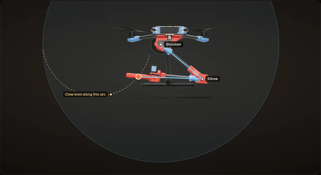
The shoulder and the elbow turn about their real axes in the CAD. Here the arm is in its CAD pose: q1 = -39.7° and q2 = -142.3°, with L1 = 235.4 mm and L2 = 278.9 mm.
Out to full reach
The orange target moves out, and the inverse kinematics turns the shoulder and the elbow to keep the claw on it. Almost straight, the arm reaches just over 500 mm here; the full reach is L1 + L2 = 514.3 mm.
Everywhere it can reach
The shaded ring is everywhere the claw can reach, from 43.5 mm to 514.3 mm from the shoulder. The target runs around its edge under the drone.
No wrist
The claw is fixed to the forearm, so its angle is whatever q1 + q2 makes it. It is level, as in the CAD, only along one arc: a circle of radius L1 around a point L2 behind the shoulder. Along the dashed arc the claw’s tilt stays at 0°, all the way back to the pose in the CAD.
In the grab above, the drone holds where the bottle sits on that arc, so the drone’s position does the job a wrist joint would.
The planned control, worked out on the CAD; it never ran on the arm. The joint limits here only keep the arm under the drone; the real ones are not in the CAD. The near half of the drone is cut away so the arm reads in profile.
What happened
Jul 7, 2025
The drone
The lab’s X500 quadcopter, the frame the arm is designed around. Dates are from the photos.
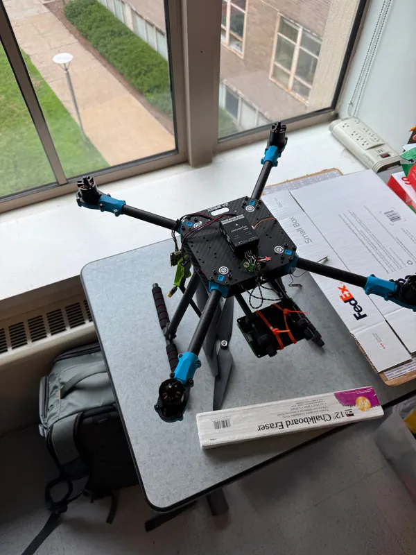
The X500 quadcopter on a desk in the lab Jul 14, 2025
Joints and links
The shoulder wedge with its servo, the carbon links and the elbow, assembled into the arm.
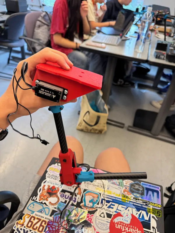
The shoulder mount and servo on the first link, with the elbow below 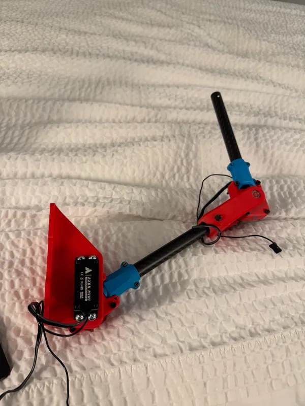
The assembled arm: the red shoulder wedge and servo, a carbon link, the elbow and the second link Jul 15, 2025
More links and the claw parts
Spare drone arms with their motor mounts, and the printed claw parts on the desk behind them.
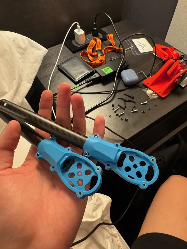
Spare carbon drone arms with their blue motor mounts, and red printed claw parts behind Then
We pivoted
The whole arm was built and almost ready to go on the drone when we pivoted to a new idea: the Hybrid Detachable UAV-UGV, a drone and a ground rover that dock together, so each one can carry the other. We felt it was the better idea because it would have more applications, and it was the surer bet in the time we had left, less than two weeks. The same team went on to build it.


