← All projectsScience OlympiadMar 2026
Science Olympiad Electric Vehicle 2026
2025-26 Electric Vehicle event
A steered car for the 2025-26 Electric Vehicle event: two versions, from servo steering to a digital caliper and linkage that sets the steering angle in 0.01 mm steps.
My second Science Olympiad electric vehicle. For 2025-26 the event stopped rewarding speed: a run is scored on how close the car stops to the target, how close it comes to a target time of 10 to 20 seconds, and a new bonus for driving between two cans set about a meter off the straight line. Earning that bonus means driving a curve, so this car came down to steering precisely.
It went through two versions. I designed the first in less than a day, to have a car ready for competition; it steered with a servo, and the backlash in the servo made the steering inaccurate. For the second I chose caliper steering: a linkage on a digital caliper sets the steering angle precisely.
Both versions in my CAD
The rear drive, electronics and battery are the same in both. The front end is where they differ: a servo right on the fork in version 1, and a bearing, a link and a digital caliper on a long aluminum spine in version 2.
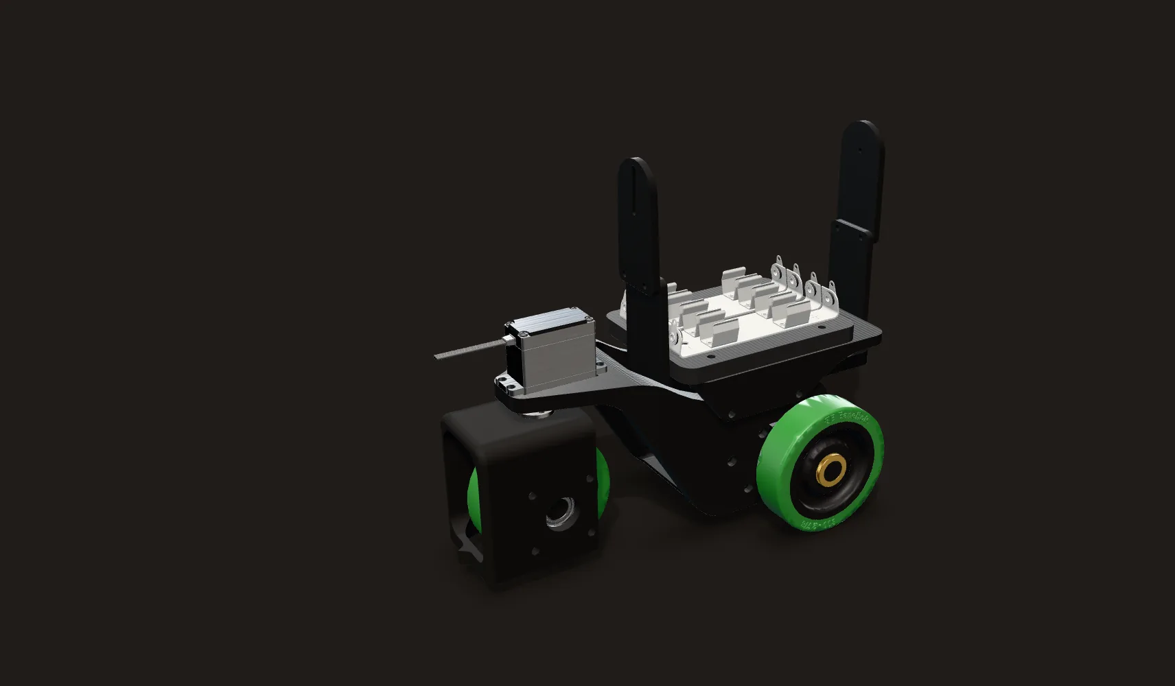
Version 1: servo steering
Two modules on a short 3D printed chassis: the brushless motor and the driven rear axle at the back, a printed fork holding one wheel at the front, and the eight AA batteries on top. The two slotted sight plates still stand at the back in this CAD; they never went on the car (Aiming).
The servo is the steering axis
The fork bolts straight to the horn of a 25 kg servo, so the servo’s output shaft is the steering axis. Any play in the servo’s gears is play in the steering.
Version 2: caliper steering
The same rear drive, electronics and battery. The front wheel moved about 310 mm forward onto a spine of two 2020 aluminum extrusions, for a 452 mm wheelbase, and a digital caliper lies along the spine.
Bearing, link and caliper
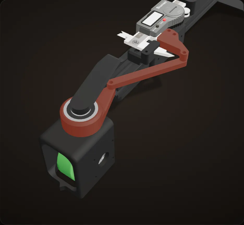
The fork turns on a 6202 ball bearing now instead of the servo’s gearbox. An arm on the bearing holder, a printed link and a clamp on the caliper’s sliding jaw set the angle (how it works).
My CAD of both versions, with only the four motor screws, and a circlip and a pin inside the motor, left out.
The rule change
My 2025 car was built for speed. That event scored a car on how quickly it covered a set distance and how close to the target it stopped, and it covered 8.3 m in 2.97 s. For 2025-26 the rules changed in two ways that decided this design:
- Time is a target now. The event supervisor picks a target time between 10.0 and 20.0 s, in half-second steps, and the Time Score is the gap between that and the run time. Fast is no longer better; accurate is.
- The can bonus. Two cans stand on a bonus line halfway between the start and the target. The outer can’s inside edge is 100 cm from the straight line between them, and we place the inner can anywhere from 0 to 100 cm inside it. The bonus is −0.5 × (110 − the gap in cm), and it only counts if every part of the car passes between the cans. The closer the cans, the bigger the bonus.

The other rules that shaped the car: a target distance of 7 to 10 m, a Distance Score of 2 points for every centimeter the car stops from the target, at most eight AA batteries, no more than 70 cm from the front of the front wheel to the back of the rear wheels, no wider than 35 cm, and a start by pressing the car with an unsharpened pencil.
My car is 13 cm wide (in my CAD).
Calculation What is the can bonus worth?
| Can bonus | −0.5 × (110 − gap in cm) points | the 2025-26 rules |
|---|---|---|
| Distance Score | 2 points per cm from the target | the 2025-26 rules |
| Car width | 13 cm | measured from the CAD |
- Through a 20 cm gap: 0.5 × (110 − 20) = 45 points, and 45 / 2 = 22.5 cm of stopping distance
- A gap only just wider than the car's 13 cm: at most 0.5 × (110 − 13) = 48.5 points, worth 24.3 cm
- Each centimetre narrower: 0.5 points, the same as stopping 2.5 mm closer
Through a 20 cm gap the bonus is worth as much as stopping 22.5 cm closer to the target; from there, each centimetre tighter adds only as much as 2.5 mm of stopping.
Lower scores win, so the bonus is subtracted. Rules as summarized above.

Why a curve needs precise steering
The car sets its steering once before a run and holds it, so it drives a circular arc. To swing out between the cans and still finish on the target, the arc has to pass the bonus line at the right distance off the line and come back. That fixes its radius, and the wheelbase turns the radius into a steering angle: steering angle = atan(wheelbase ÷ radius).
| Track length | Arc radius | Version 1, 142 mm wheelbase | Version 2, 452 mm wheelbase |
|---|---|---|---|
| 7 m | 7.26 m | 1.12° ± 0.04° | 3.57° ± 0.14° |
| 8.5 m | 10.48 m | 0.78° ± 0.03° | 2.47° ± 0.10° |
| 10 m | 14.34 m | 0.57° ± 0.02° | 1.81° ± 0.07° |
Every setting the can bonus needs is a few degrees at most. On version 1 it is about a degree, and it has to be right to a few hundredths of a degree.
Version 1: servo steering
I designed version 1 in less than a day, to have a car ready for the competition. It is two modules on a short 3D printed chassis. The rear module carries the brushless motor and the driven rear axle. The front module is a printed fork holding one wheel, and the fork bolts straight to the horn of a 25 kg servo (a DS3225MG in my CAD), so the servo’s output shaft is the steering axis. The eight AA batteries ride on top. Wheelbase 142 mm, width 130 mm (in my CAD).
In the code the steering setting is a whole number of degrees, written to the servo once at startup, with 90 as straight ahead.
Problem Backlash in the servo
The backlash in the servo made the steering inaccurate. That play sits right on the steering axis, and on a 142 mm wheelbase the settings the can bonus needs run from about half a degree to a degree, each with a few hundredths of a degree to spare (computed, table above). Whole degrees were too coarse as well: 1° is already an 8.1 m radius and 2° is 4.1 m (computed).
Fix
Version 2 takes the servo out of the steering completely and sets the angle with a caliper and a linkage.


What the play does to a run
One track, to scale, and the same small error in the steering on both cars.
The plan
An 8 m track with the inner can 30 cm inside the outer one. To pass through the middle of that gap and still finish on the target, version 1 steers 0.83° and holds it: an arc of 9.8 m radius, aimed 24° out at the start (computed).
A quarter of a degree of play
This picture assumes just ±0.25° of play in the steering, a guess and not a measurement. The shaded band is everywhere the car can go: at the cans it runs from 60 to 111 cm off the line, wider than the whole gap, and the stop moves by up to about a meter (computed).
Three runs
Three runs with errors inside that play: −0.18°, +0.07° and +0.22°. Only the middle one passes between the cans, and the three stop 74, 29 and 89 cm from the target. At 2 points of Distance Score per centimeter, that is 148, 57 and 179 points (computed).
Whole degrees
My code wrote the steering as a whole number of degrees. The nearest settings to 0.83° are 0° and 1°: 0° drives straight down the line, and 1° is an 8.1 m arc that passes 105 cm out, outside the outer can. Neither goes through the gap, even with no play at all (computed).
Version 2, same play
The same track and the same assumed play on version 2. Its 452 mm wheelbase needs 2.63° for the same arc, 1.21 mm of caliper travel, so the same error bends its path about 3.2 times less. The whole band passes between the cans, the same three errors stop 23, 9 and 28 cm from the target, and the worst case is 32 cm (computed).
Top view of a track, to scale, from the rules’ track layout and the wheelbases in my CAD. The model: the steering is set once and held, the car is aimed so the planned arc ends on the target and drives the planned arc length, and the wheels do not slip. The ±0.25° of play is an assumption, not a measurement, and the three errors are picked inside it.
Version 1 did run at competition before version 2 existed.
Version 2: caliper steering
For version 2 I chose caliper steering. A digital caliper sits along the car’s spine, and a linkage turns the position of its sliding jaw into a steering angle. It let us set the steering angle precisely. How it works, from my CAD:

- Same fork, new pivot. I kept version 1’s printed fork, wheel and axle. Where the fork’s four screws went into the servo horn, they now go into a printed bearing holder that turns on a 6202 ball bearing (14 mm bore, 35 mm outside, per the part in my CAD). The steering axis is a bearing now instead of the servo’s gearbox.
- Arm, link, slider. The bearing holder has a 50 mm arm pointing back along the car. A printed link, 89.4 mm between its pins, joins the end of that arm to a clamp on the caliper’s sliding jaw. The clamp’s pin slides along a line 44.2 mm to one side of the steering axis.
- Travel to angle. Sliding the jaw back pulls the link and swings the arm, which steers the wheel right; sliding it forward steers left. Near straight ahead, 1 mm of jaw travel is about 2.0° of steering, so one 0.01 mm count on the caliper is about 0.02° (computed from my CAD).
- A longer car. The front wheel moved about 310 mm forward onto a spine of two 2020 T-slot aluminum extrusions (184.5 mm and 88.5 mm long), for a 452 mm wheelbase. The rear drive, electronics and battery stayed where they were. The car is 525 mm from the front of the front wheel to the back of the rear wheels, inside the 70 cm limit.

The longer wheelbase changes the math on its own: the same arc needs a bigger steering angle, so a fixed error in the angle moves the car about 3.2 times less than on version 1 (computed).

Caliper in, steering out
Version 2’s front end in my CAD. As you scroll, the caliper’s jaw slides, and the link and the fork turn about the real pivot axes in my CAD. The readout is the geometry of those pivots.
Straight ahead
The linkage is a slider and crank. The clamp on the caliper’s sliding jaw carries the link’s rear pin along a line 44.2 mm to one side of the steering axis, and the link’s front pin turns a 50 mm arm on the bearing holder. The orange line on the floor follows the wheel’s heading.
Opening steers right
Sliding the jaw back pulls the link and swings the arm, which steers the wheel right. 1.21 mm is the setting for the track above: 2.63° and a 9.8 m arc (computed).
Closing steers left
Sliding it forward steers left: 2 mm of closing is 3.65° and a 7.1 m arc (computed). Around straight ahead the response is close to linear, about 2.0° per millimeter.
Steeper near the end
It gets steeper as the link and the arm come into line, which in my CAD happens at about 4.5 mm of opening; at 4.2 mm, one millimeter is already about 8° (computed). The settings a track needs, about 1 to 2 mm either way, sit in the gentle part.
One count on the caliper
Back at 1.21 mm, then five counts of 0.01 mm, one count on the caliper each. Each turns the wheel about 0.024°. The table above gives version 2 between ±0.07° and ±0.14° of room, so several counts (computed).
A printed link
Problem A printed link
The link was 3D printed, which limited its accuracy.
It was still much more accurate than the servo.
My CAD of version 2. The link and the fork follow the real pivot axes. Angles and radii are computed from the linkage in my CAD (50 mm arm, 89.4 mm link, 44.2 mm offset) and the 452 mm wheelbase, with zero at the CAD pose. The orange line on the floor is an annotation that follows the wheel’s heading; the pale one is straight ahead.
Tuning it
I tuned it on the floor at home: set the caliper, line the car up against a tape measure on the floor, press start, see where it stops, change the setting, and go again.


Drive and electronics
- A D2830 brushless motor (1000 KV, per the part in my CAD) drives the rear axle through an 8 tooth pinion. The code counts 6 turns of the encoder for every turn of the wheels.
- An MT6701 magnetic encoder, read over I2C, sits at the end of the pinion shaft (in my CAD).
- 2.875 in BaneBots wheels.
- An Arduino Nano Every runs everything. The motor’s speed controller takes standard servo pulses: 1500 µs is stop and 2000 µs is full power.
- Eight AA batteries in a removable pack (below).
The electronics module comes straight from my 2025 car (the CAD part is still named for 2024-25), and so do the motor, the encoder mount, the wheels and the pinion.

Calculation Can the encoder sit on the pinion shaft again?
| Encoder turns per wheel turn | 6 | my code |
|---|---|---|
| Wheel | 2.875 in: 229.4 mm around | BaneBots wheel, in the CAD |
| MT6701 angle over I2C | 14 bits: 16,384 steps per turn | MagnTek MT6701 datasheet |
| Target distance and time | 7 to 10 m, 10 to 20 s | the 2025-26 rules |
- Travel per encoder turn: 229.4 mm / 6 = 38.2 mm, and per step 38.2 / 16,384 = 0.002 mm
- The code must read the magnet at least every half turn: 19.1 mm of travel
- Fastest run the rules allow, 10 m in 10 s: 1.0 m/s, so 19.1 mm / 1.0 m/s = 19 ms per loop
- On the 2025 car at 2.8 m/s the same ratio left 6.8 ms
A target-time car drives at most about 1 m/s, so even at 6 turns per wheel turn the loop has about 19 ms, nearly three times what that ratio left on the 2025 car.
Constant speed assumed; the car speeds up to its target speed, so it can briefly run faster. See the 2025 car for why the encoder was geared down there.

The code
The code is on GitHub: github.com/jerryli08/sciolyev2026. It is four Arduino sketches. code.ino is my 2025 car’s control loop with a steering servo added and the encoder ratio changed. targetTimeCode.ino, fairfaxCompCode.ino and finalCompCode.ino share one target-time loop and differ in their track settings and speed-controller gains.
Every loop of the target-time code:
- Debounce two buttons. One toggles a laser output; the other starts and stops the run.
- Read the MT6701’s angle, unwrap it across 0 and 360 degrees, and turn the change into distance: change in angle ÷ 360 × wheel circumference ÷ 6.
- Work out speed from that distance and the loop time.
- Until 5 cm before the target distance, a speed controller holds the car at target distance ÷ target time.
- In the last 5 cm, a position controller brings the car to the target distance.
- Add a fixed 0.08 to any forward command, and send it to the motor’s speed controller as a pulse from 1500 to 2000 µs.
distance += -(Δangle / 360) × (π × 2.875 in) / 6        the encoder counts backwards
if distance < targetDist - 5 cm:
    power = speedPID(targetDist / targetTime - speed)
else:
    power = positionPID(targetDist - distance)
esc pulse = 1500 µs + 500 µs × (power + 0.08 if power > 0)
The settings that change for each track sit together at the top of the file under ADJUSTABLE PARAMETERS (EASY ACCESS): the target distance, the target time and, for version 1, the steering angle. In finalCompCode.ino a comment says the servo isn’t used anymore; on version 2 the caliper sets the steering.
Problem Runs came out long
Set to 15 s, a run might take 16. In the final code I left a note that the timing was not reliable, and that our battery may have been low at Penn.
Fix
We corrected by hand: if a layout needed 15 s, enter 14. I also suggested keeping a spreadsheet of track layouts, each with the can’s sideways offset and the distance, and the settings that worked.

Running it at competition
I filmed short how-to videos for running the car at a competition: loading the batteries, fitting the pack, uploading the code from the Arduino IDE, changing the settings, impound, and starting a run with a pencil.
A battery pack that comes off in one piece
At impound the batteries have to be off the car. The eight cells live in one pack: it slides into a slot on the car, a hand-tightened nut holds it, and one plug connects it, so the whole pack comes off with the cells still in it.
Problem A fragile plug
I made that connector myself, and it was fragile.
Workaround
Handle it gently. The impound how-to says exactly that: unplug it gently, slide the pack out, keep the cells in it, and bag it with the nut.

Aiming
Problem The sight did not fit
I designed a sight for aiming the car: two slotted plates to look along. I did not realize the battery was going to be in the way, so it never went on.
Fix
We aimed by eye, and at a competition on January 17 we lined the car up with a protractor at the start.


Timeline
Jan 6, 2026
Starting from the 2025 car
The evening I started designing version 1. The drive, the encoder mount and the electronics came from my 2024-25 car.
Jan 7 to 8
Version 1 in CAD, then printed and wired
The finished CAD by the evening of January 7; soldering, the printed chassis and the servo on January 8.
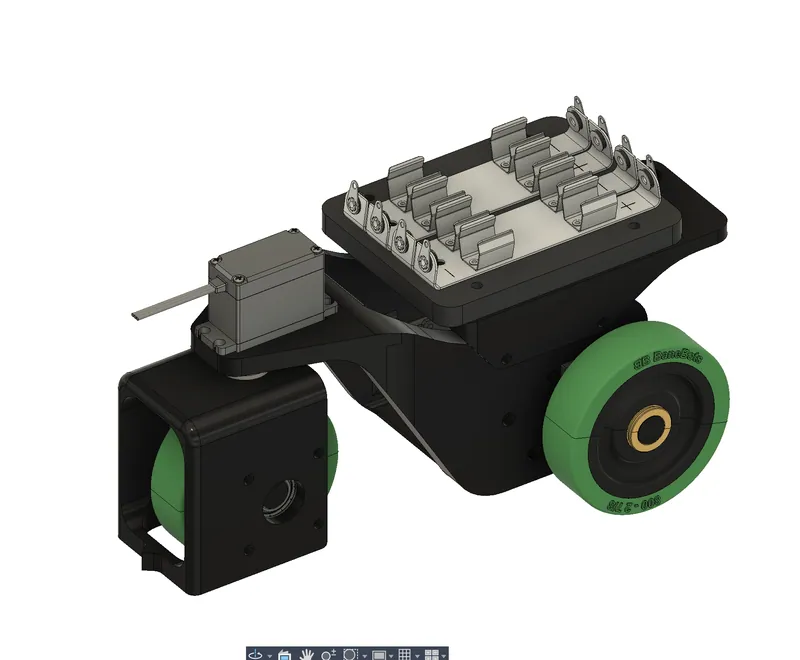
Version 1 in my CAD, with the battery holders on top 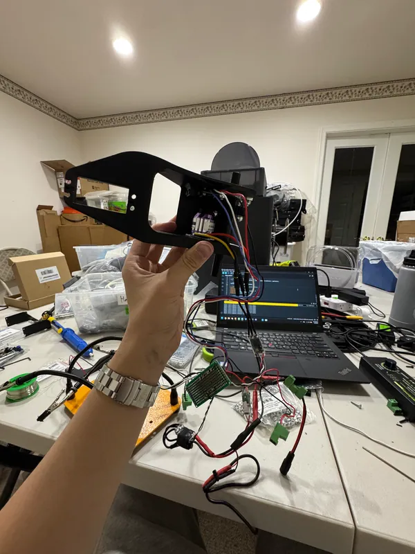
The printed chassis with its electronics 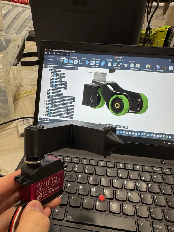
The servo in hand, the front module’s CAD behind it Jan 17
Version 1 at a competition
Aimed with a protractor at the start and run out toward the cans (both above).
Feb 13 to 14
Version 2: caliper steering, then tuning
The caliper and the printed link on February 13, the finished car that night, and tuning runs on the floor right after.
Later
Version 2 at a competition
Started with a pencil and out to the cans on the bonus line (the first video at the top of this page).


From the 2025 car
| 2024-25 car | 2025-26 car | |
|---|---|---|
| Scoring | How quickly it covers the distance, and how close to the target it stops | Target time (10 to 20 s), stop distance and a can bonus |
| Layout | Four wheels, all-wheel drive | Three wheels: a driven rear axle and one steered front wheel |
| Chassis | 1.5 mm G10 fiberglass lattice plates, designed with FEA | 3D printed (version 1); 2020 aluminum extrusion spine (version 2) |
| Steering | None | Servo (version 1); caliper and linkage (version 2) |
| Encoder | MT6701; 1.2 encoder turns per wheel turn in the code | Same encoder mount; 6 encoder turns per wheel turn |
| Control | Ramp up, full power, then position control to the target | Hold distance ÷ time, then position control to the target |