← All projectsScience OlympiadSep 2024 to Jan 2025
Science Olympiad Electric Vehicle 2025
2024-25 Electric Vehicle event
A precision-stopping race car that took 1st at regionals and 2nd of 72 at the UPenn Invitational.
I designed and built this car by myself for the 2024-25 Science Olympiad Electric Vehicle event, which scores a car on how quickly it covers a set distance and how close to the target it stops. One brushless motor drives all four wheels through a 6 : 1 printed gear pair and two GT2 belts, a geared magnetic encoder measures the distance, and an Arduino schedules the power on distance so the car slows as it closes on the target.
The chassis is two 1.5 mm G10 fiberglass plates with a lattice I designed with FEA so the car can twist over bumps in the floor. It covered 8.3 m in 2.97 s and stopped 1.1 cm from the target, and took 1st of 48 at the East Maryland Regional.
How it works
Five views of my final CAD, one per mechanism. The top plate fades away while the gears are on screen and comes back for the buttons. The drivetrain turns as you scroll, every part at the speed its tooth count gives it.
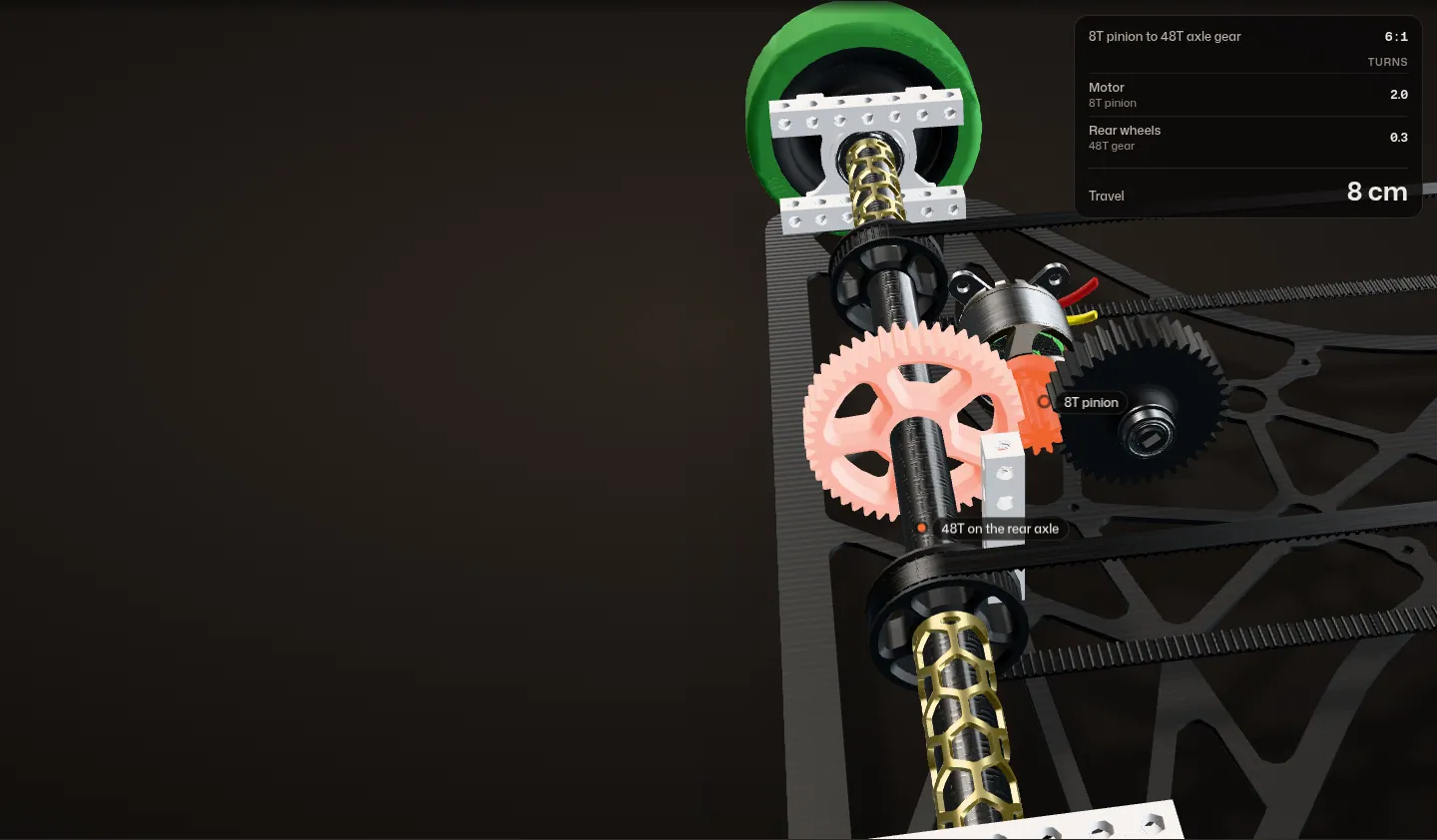
1. The geared drivetrain
One D2830 brushless outrunner sits on a printed mount at the back of the car; the label on the real motor reads 850KV. Its 8-tooth pinion drives a 48-tooth gear on the rear axle, a 6 : 1 reduction.
The gears are 3D printed. In the CAD their centres are 28 mm apart, which is (8 + 48) / 2: module 1. The axle is a 12 mm carbon fiber tube in goBILDA pillow blocks, with 2.875 in BaneBots wheels on the ends.
2. The geared encoder
The same pinion also drives a 40-tooth gear on its own short shaft, and an MT6701 magnetic encoder reads that shaft's angle. It turns at a fifth of motor speed: 1.2 turns per wheel turn (48 / 40; the code uses the same 1.2).
On my first version the encoder read the motor shaft directly, 6 turns per wheel turn. I had to gear it down because of loop times; the section below shows why.
3. The belts to the front
Two 1140 mm GT2 belts run the length of the car on 47-tooth pulleys, one on each side, from the rear axle to the front axle. At 1 : 1 the front wheels turn exactly with the back wheels, so all four wheels drive. That decreases wheel slip and increases speed.
Slip matters twice on this car: the encoder is geared to the drivetrain, so it counts wheel turns, not ground covered. The spacers on the axles are printed honeycomb tubes.
Belt check from the CAD: 2 x 523.1 mm between the axles + pi x 29.92 mm pitch diameter = 1140 mm.
4. Two buttons
Two buttons sit in a printed plate on top, at the back. The left one toggles the laser pointer on the front of the car. The right one starts the run.
In the code they are debounced inputs on pins 7 and 4, read at the top of every loop.
5. The whole car
Two 287 x 590 mm G10 plates, 1.5 mm thick, 40 mm apart on goBILDA beams, with the electronics between them. The wheelbase is 523 mm and the track 320 mm (CAD): about 30 by 60 cm overall.


Why the encoder had to be geared down
The Arduino reads the MT6701's absolute angle once per loop and adds the change since the last read to a running distance. It decides which way the magnet moved by taking the shorter way around the circle, which only works if the magnet turned less than half a turn between two reads.
One loop of the code
Between two reads the magnet turns (the dashed ring). The code only sees the new angle and takes the short way round from the last one (the solid arc).
The speed here is the car's average over 8.3 m in 2.97 s: 2.8 m/s. With a short loop the magnet turns a little between reads, and the count is right.
Version one: the encoder on the motor shaft
Problem The encoder on the motor shaft
On version one the MT6701 read the motor shaft, so it turned 6 times for every turn of the wheels. Half a turn of the magnet was only 19.1 mm of travel.
At 2.8 m/s the loop would have had to finish in under 6.8 ms, every time, and faster still at top speed.
Past half a turn
Miss that and the code reads the magnet turning the wrong way, and the distance count goes wrong. Past half a turn the code reads it backwards, and the distance it counts for an 8.3 m run falls apart.
Version two: gear it down
Fix Gear the encoder down
In version two the encoder rides on a 40-tooth gear driven by the motor pinion, 1.2 turns per wheel turn. Half a turn is now 95.6 mm of travel.
Five times the headroom
The same 2.8 m/s leaves 34 ms per loop: five times the headroom. In the code the change is one constant,
gearRatio, from 6.0 to 1.2.Numbers from the wheel size (2.875 in, 229.4 mm around) and the tooth counts.
Constant speed and no noise: this shows the sampling limit only. The loop times are swept to show the limit; they are not measured from my code.
Version one to version two
Version one used CNC-cut HDF plates. They were heavy, and too stiff: I knew the chassis needed to flex over floor bumps. The G10 plates arrived on January 9, 2025, and I started rebuilding the car on them the same day.
Problem Heavy and too stiff
Each HDF plate weighed 369 g on my scale. And the chassis was too stiff: a car that cannot twist sits on three wheels as soon as the floor is uneven, and with every wheel driven, an unloaded wheel is lost drive.
Fix An FEA-designed G10 lattice
I used Fusion 360 FEA to design a lattice into 1.5 mm G10 fiberglass plates that gives the chassis torsional flexibility, so the car passively absorbs bumps in the floor. The wide ends of each plate are open, irregular cells; the narrow spine between them is a row of hexagons between two rails, tied across.
Each G10 plate weighs 99 g. The two main plates went from 738 g to 198 g, 73% lighter, and the run time dropped from about 15 s to 2.9 s.

Calculation What does the lighter car buy?
| Whole car on my scale, version one | 1,645 g | my scale photo |
|---|---|---|
| Whole car on my scale, version two | 1,394 g | my scale photo |
- 1,645 g - 1,394 g = 251 g lighter, 15 %
- For the same drive force, acceleration goes as 1 / mass: 1,645 / 1,394 = 1.18
With the same push from the motor, version two would accelerate about 18 % harder, with 15 % less mass to stop at the target.
Same force assumed; version two also changed its motors and drivetrain, so this is only the weight's share.

Both versions in CAD
My two CAD files, one after the other. Version one's plates are tinted brown like the real HDF. Screws are left out of both models, and so is version one's STM32 board.
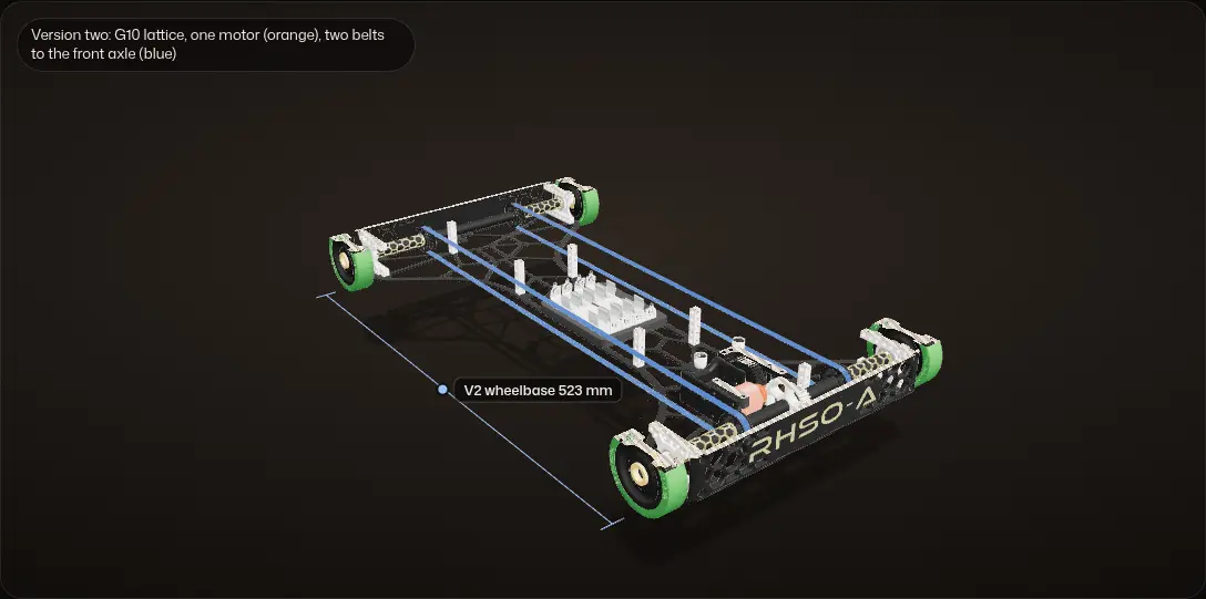
Version one: HDF plates
CNC-cut HDF plates, 287 x 690 mm, with a 623 mm wheelbase (CAD).
Two motors
Between the plates: one D2830 geared to each axle, and the encoder on the rear motor's shaft, 6 turns per wheel turn. The controls were an STM32 Nucleo board, a 16x2 LCD and three buttons.
Version two: one motor and belts
One D2830 drives all four wheels, the rear axle through the gears and the front axle through two GT2 belts. The encoder rides on a 40T gear, 1.2 turns per wheel turn, and an Arduino Nano with two buttons replaced the STM32 board and the LCD.
The same car, 100 mm shorter
Version one as a ghost over version two: the same car with 50 mm more at each end. The plate outline went from 287 x 690 mm to 287 x 590 mm and the wheelbase from 623 mm to 523 mm.
The G10 lattice
From above, top plate back on: open cells at the wide ends, hexagons between two rails along the spine.
| Version one | Version two | |
|---|---|---|
| Main plates | HDF, solid, CNC cut | 1.5 mm G10 fiberglass, lattice |
| One plate on my scale | 369 g | 99 g |
| Plate outline (CAD) | 287 x 690 mm | 287 x 590 mm |
| Wheelbase (CAD) | 623 mm | 523 mm |
| Motors (CAD) | Two D2830s, one geared to each axle | One D2830, belts to the front axle |
| Encoder (CAD) | On the motor shaft: 6 turns per wheel turn | On a 40T gear: 1.2 turns per wheel turn |
| Controls (CAD and code) | STM32 Nucleo board, 16x2 LCD, three buttons | Arduino Nano, two buttons |
The torsion FEA, re-run
A new run of the torsion study, on the plate from my final CAD, next to a solid plate with the same outline.
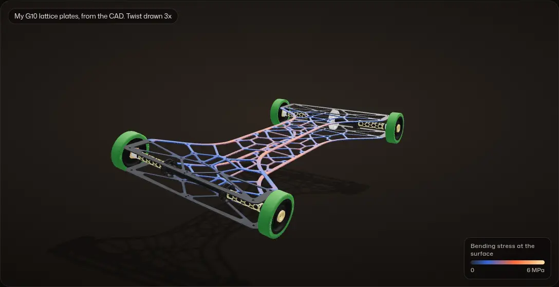
Held at the pillow blocks
Each plate is held where the pillow blocks bolt through it. The rear pair stays put and the front pair turns about the car's long axis.
One front wheel over a bump
That is the way the chassis twists when one front wheel rides over a bump. The colour is the bending stress at the surface.
A solid plate, same outline
The lattice keeps 34% of the plate's material (322 of 944 cm²) and 28% of its torsional stiffness: 10.6 N·mm per degree of twist against 38.0 for the solid plate.
Flexible, without piling up stress
At the same twist, the highest bending stress is nearly the same in both, about 1.3 MPa per degree, so the lattice gives up stiffness without piling stress into its rails.
Plate model (Kirchhoff plate, 1 mm elements) of one main plate, with assumed typical values for G10: E = 18 GPa, Poisson's ratio 0.12, isotropic. E sets the absolute numbers; the lattice-to-solid ratio does not depend on it. Both plates twist together, so the chassis is at least twice one plate; the beams tying the two plates make it stiffer than that, and this model leaves them out. The solid plate is generated from my outline, not a CAD part. The bending and the front axle's tilt are drawn 3 times larger than real; the readouts are not.
Iterations
Version one
HDF plates, two motors (December 2024)
CNC-cut HDF plates, one D2830 geared to each axle, and the encoder reading the rear motor's shaft. My first code for it ran on an STM32 Nucleo board; those sketches are in the repo's
deprecatedfolder. The first ground test ran the rear half on a cable.On my scale the whole car read 1,645 g in this photo, with the plates alone 738 g of it.
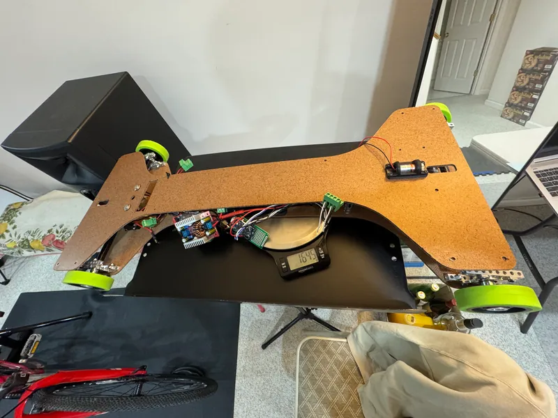
Version one on HDF plates, on my scale: 1,645 g The printed 48T gear turning on the carbon axle Version one's rear half on the carpet, driven on a cable Version two
G10 lattice, one motor and belts (January 2025)
The FEA-designed G10 plates, 100 mm shorter, one motor driving all four wheels through the gears and two GT2 belts, and the encoder geared down to 1.2 turns per wheel turn. The finished car read 1,394 g on the same scale.
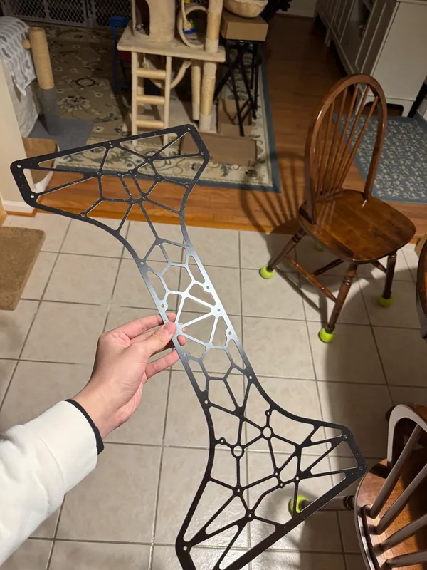
A G10 plate, the day the plates arrived 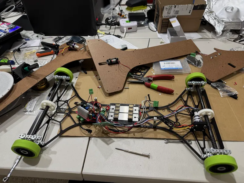
The same day: the car rebuilt on G10, with an old HDF plate behind it 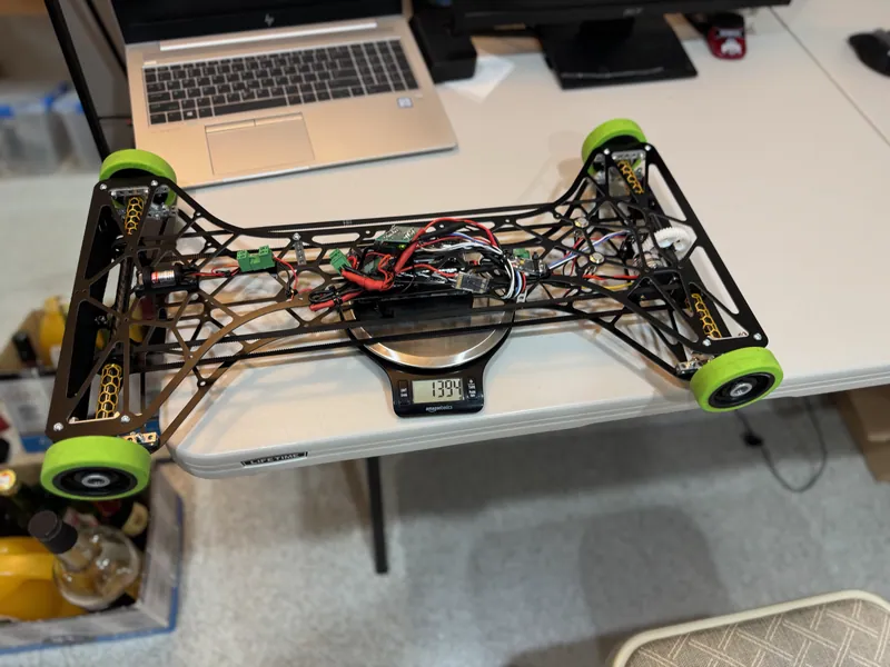
Version two, finished, on my scale: 1,394 g


The code
All of the car's code is on GitHub: github.com/jerryli08/sciolyEv. It is one Arduino sketch per stage of the project, from the first motor test to the final distance profiles.
One polling loop
Everything runs in one loop on the Arduino Nano. Each pass it:
- reads the two buttons, debounced over 30 ms: the left one toggles the laser, the right one starts and stops the run;
- reads the MT6701's absolute angle over I2C and adds the change since the last pass to a running distance, taking the shorter way around the circle (the step that forced the geared encoder);
- converts angle to distance with the wheel's circumference (2.875 in wheels) divided by the encoder ratio (1.2);
- picks a power command from the distance travelled;
- sends it to the ESC as a servo pulse: 1500 µs is neutral, 2000 µs is full forward and below 1500 µs is reverse, so the same number can drive or brake;
- prints power, distance and target over serial at 500,000 baud, which I plotted live while tuning.

Calculation How fine is one count of the encoder?
| MT6701 angle over I2C | 14 bits: 16,384 steps per turn | MagnTek MT6701 datasheet |
|---|---|---|
| Wheel | 2.875 in: 229.4 mm around | BaneBots wheel, in the CAD |
| Encoder turns per wheel turn | 1.2 | the CAD and my code |
| The run | 8.3 m in 2.97 s, stopped 1.1 cm from the target | my result |
- Travel per encoder turn: 229.4 mm / 1.2 = 191.2 mm
- Travel per step: 191.2 mm / 16,384 = 0.012 mm
- The 1.1 cm stop error is 11 / 0.012 = about 940 steps
- At the run's average speed, 8.3 m / 2.97 s = 2.8 m/s, the car covers 1.1 cm in 11 mm / 2.8 m/s = 4 ms
The encoder resolves about a hundredth of a millimetre, a thousand times finer than the stop, so its resolution is not what sets the stop. At full speed the car crosses 1.1 cm in about 4 ms, and every sketch slows the car before the target.
Resolution only: wheel slip and tyre squash change how far the car really goes per wheel turn.
The speed profile is scheduled on distance, not time
In SOUPCode and PUSOCode the car ramps power up over the first 1.8 m, runs at full power, and 3 m before the target hands over to a PID controller (ArduPID) whose setpoint is the target distance. It only uses the proportional term, 0.002 per cm of distance left, plus a constant feedforward of 0.08 while the command is positive. Its output can go negative: if the car passes the target, the motor reverses and pulls it back.
regionalsCode ramps the power down on a fixed schedule over the last 3 m instead, and creeps the final 20 cm at a constant 0.08. In every sketch the target is a single constant at the top of the file.

How each sketch brings the car in
The power command each sketch sends, against the distance the encoder has counted, over the last 4 m before its target, oldest sketch first. The car runs in as you scroll, and the readout shows the command and the ESC pulse where it is.
fullEvCodeMy first closed loop, forward only: power proportional to the distance left (gain 12.5, so it stays at full until the end), cut 60 cm before the target, then the car coasts in.
AWDGearedEncoderCodeAn earlier test with the geared encoder: full power until 2 m out, proportional to 50 cm, then a slow creep. The small offsets after the clamp push the command just past full.
regionalsCodeFull power, then from 3 m out the power ramps down on a fixed schedule, creeps the last 20 cm at 0.08 and stops at the target.
SOUPCodeandPUSOCodeFull power, then from 3 m out a P controller on position (Kp 0.002 per cm) plus 0.08 feedforward while it drives forward. Past the target the command goes negative: the motor reverses. The two are the same sketch with a different target, 823 and 888 cm.
Transcribed from the sketches in the repo; no physics. Each sketch is drawn against its own target: 700 cm in fullEvCode, 495.7 cm in AWDGearedEncoderCode and 823 cm in the last two. The distance comes from the encoder: angle change x 229.4 mm / 1.2 per turn (6.0 in fullEvCode).
How it got there
The repo keeps every stage as its own sketch:
deprecated/: my first motor tests, on the STM32 Nucleo.MT6701TestandintegratedDriveCode: reading the encoder, then a first closed loop that cut power in proportion to the distance left.fullEvCode: the full run, with a correction factor on the wheel circumference, stopping the motor 60 cm early and coasting in.frontWheelDriveTest,AWDcode: the ESC set up for both directions (1500 µs neutral), front-wheel drive and then all-wheel drive, still with the encoder on the motor (ratio 6.0).AWDGearedEncoderCode: the geared encoder, ratio 1.2.AWD_PIDTest, thenregionalsCode,SOUPCodeandPUSOCode: the distance-scheduled profiles above.
Problem Coasting onto the target
My first closed loop could only drive forward. It cut the motor 60 cm before the target, a constant the code calls overshoot, and let the car coast in, so where it stopped depended on its momentum.
Fix Let the controller brake
I set the ESC up for both directions, with 1500 µs as neutral, so the approach could become a controller on position whose output goes negative: past the target, the motor reverses and pulls the car back.

Electronics
An Arduino Nano reads the MT6701 magnetic absolute encoder over I2C and drives the motor's ESC with a servo pulse. The ESC is an AIKON AK32 35A, as its label reads, tuned in BLHeli_32 Suite. The electronics sit on perfboard between the two plates.


Testing
I tested in long hallways: at home on wood and tile, then in two school hallways with tape marks for the target, running the same distance again and again with the laptop on the floor between runs.
Results
1st of 48 at the East Maryland Regional, 2nd of 28 at the Maryland State Championship, 2nd of 72 at the UPenn Invitational (behind the team that went on to win nationals), and 4th of 57 at the Princeton Invitational.
It covered 8.3 m in 2.97 s and stopped 1.1 cm (0.13%) from the target.
More pictures


