← All projectsScience OlympiadMar 2026
Science Olympiad Machines
2025-26 Machines event
A compound lever that measures mass ratios: a class 1 lever joined to a class 2 lever by a rigid link.

A measuring device for the Science Olympiad Machines event, where you are handed test masses and have to find the ratios between them. It is a class 1 lever joined to a class 2 lever by a rigid link: hang one mass on each, slide them until the device sits level, and the two positions give the ratio.
I built it from 2020 aluminum extrusion, 3D-printed mounts and ball bearings. The link multiplies the upper lever’s effect by 5, so the same two rulers read ratios from about 1 : 1 up to 24 : 1.
Two levers and a link
My device for the 2025-26 Machines event, where you are given test masses and have to find the ratios between them. Scroll to see how its two levers move together.
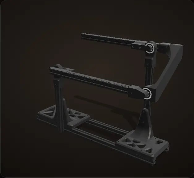
The CAD
This is the CAD of the device: two beams on two posts, each beam a lever, joined at the right end by one rigid link.
Class 1: the upper beam
The upper beam is the class 1 lever: its fulcrum sits between the mass and the link. When the mass side goes down, the link side comes up.
Class 2: the lower beam
The lower beam is the class 2 lever: its fulcrum is at one end, the link at the other, and the mass hangs in between.
The link: 5 : 1
As the upper lever tips, watch the link: both link pins move up and down by the same amount, but one is 75 mm from its fulcrum and the other 375 mm, so the lower lever turns a fifth as far. That 5 : 1 is the key to the device.
Both levers turn about the real fulcrum axes in the CAD (the bearing bores); the tipping range is a visual limit, not a stop in the CAD.
The event
Machines asks for a lever-based measuring device built before the tournament. Under the 2026 rules it has to be a class 1 lever connected directly, by a flexible or rigid link, to a class 2 or class 3 lever. Each beam can be at most 40.0 cm long, and no springs or electronics are allowed.
At the event you are given three test masses and report two ratios, A/B and B/C, as decimals. The device’s whole job is to turn "where do the two masses balance" into a number.
How the balance works
Each mass hangs at some distance from its own fulcrum: a for mass A on the upper lever, b for mass B on the lower one. With the device level, the moments on each lever cancel, and the link carries the same force T to both:
class 1 (upper):  m_A × a = T × 75 mm
class 2 (lower):  T × 375 mm = m_B × b
so:               m_A / m_B = b / (5a)
So a reading is two ruler positions and one division. Both beams carry a printed ruler that starts 65 mm from the fulcrum and runs 250.8 mm, so a and b can each be anything from 65 to 316 mm.
| Lightest ratio | Heaviest ratio | |
|---|---|---|
| With the 5 : 1 link | about 1.03 : 1 | about 24 : 1 |
| Same rulers on one plain lever | about 1 : 1 | about 4.9 : 1 |
The link is what stretches the range: without it, the same rulers would stop at about 4.9 : 1. The catch is that the lighter mass always goes on the upper, class 1 lever. Hang the heavier one there and there is no balance point on the rulers; the animation below shows that too.
Calculation How much does a misread ruler move the answer?
| Ratio from the two positions | m_A / m_B = b / (5a) | the balance above |
|---|---|---|
| Example setting | a = 200 mm, b = 285.7 mm (100 g and 350 g) | the example below |
| Ruler range | 65 to 316 mm on each beam | measured from the CAD |
| Reading error | 1 mm on each ruler | assumed |
- For a ratio of two lengths, the relative errors add: 1 / a + 1 / b
- Example: 1 / 200 + 1 / 285.7 = 0.50 % + 0.35 % = 0.85 %, so 0.286 could read 0.283 to 0.288
- Both masses at the start of the rulers: 1 / 65 + 1 / 65 = 3.1 %
- Both near the ends: 1 / 316 + 1 / 316 = 0.6 %
A millimetre misread on each ruler costs under 1 % in the example, and less the further out the masses hang: about 3 % near the fulcrums, 0.6 % near the ends.
Worst case: both misreadings push the ratio the same way (one ruler read long, the other short).
Balance two masses
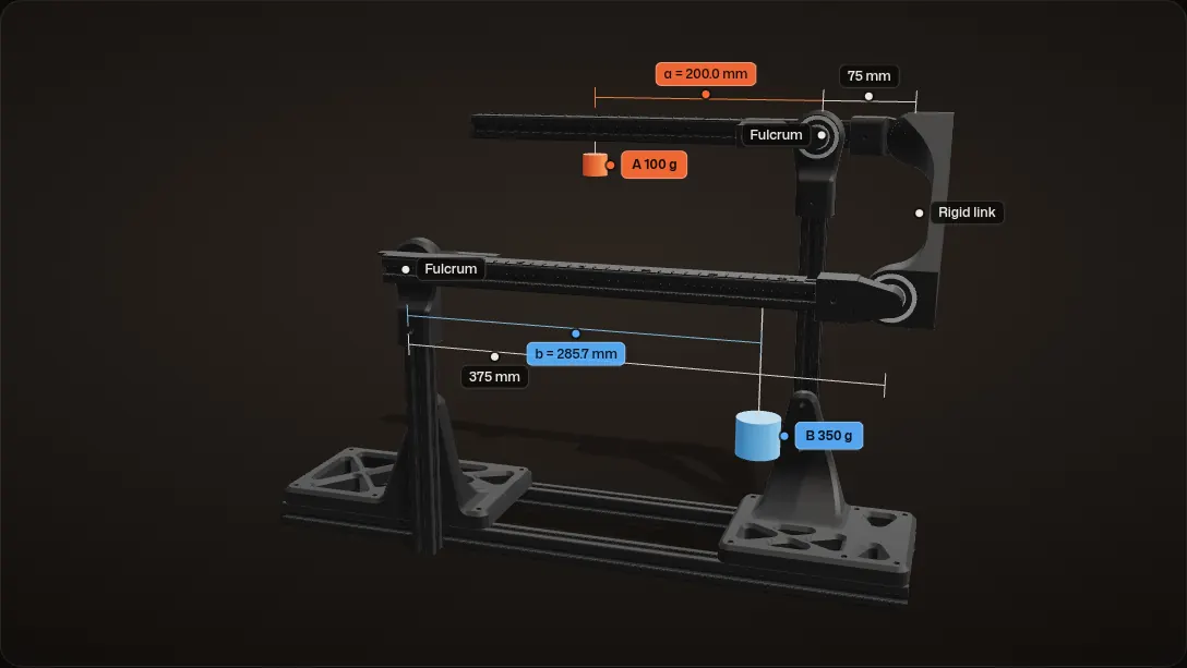
Hang mass A on the class 1 lever
Mass A, 100 g in this example, hangs 200 mm out on the upper lever. With nothing on the other lever yet, the device tips toward A.
Hang mass B on the class 2 lever
Mass B, 350 g, hangs on the lower lever at the start of its ruler, 65 mm from the fulcrum. Through the link its moment reaches the upper lever divided by 5, so A's side stays down.
Slide B out until it balances
B slides out along its ruler. The further out it hangs, the harder it pulls on the link, and at 285.7 mm the two moments cancel and the device comes level.
Level: read the ratio
Level, the two ruler positions give the ratio: m_A / m_B = b / (5a) = 285.7 / (5 × 200) = 0.286, which is 100 g over 350 g. That decimal is what you report.
The readout also gives the force in the link and how far the ratio would move if each ruler were read 1 mm off.
The heavier mass on top: no balance
Swap them, with the 350 g mass on the class 1 lever, and there is no balance point on the rulers. Even with A all the way in at 65 mm and B all the way out at 315.8 mm, A's side stays down: B would have to hang about 1,138 mm out. The lighter mass always goes on the upper lever.
Ideal balance: the weights of the beams and the link, and bearing friction, are left out. The 100 g and 350 g masses are examples, not the official test masses, and the device counts as level within 0.5% of the moment. How far it leans while off balance is drawn, and the tipping range is a visual limit, not a stop in the CAD. The masses and strings are drawn in; they are not part of the CAD.
Extrusion, prints and bearings
Both beams and both posts are 2020 aluminum extrusion, standing on a base of two 550 mm extrusion rails. The beams measure 366 mm in the CAD, inside the 40.0 cm limit. Everything that joins the extrusions is 3D printed: the lattice foot plates, the fulcrum stands on top of the posts, the fulcrum rod mounts on the beams and the link ends. The link is one rigid curved part between the two beam ends.
Each fulcrum is a ball bearing (35 mm outside, 14 mm bore) in a printed stand on top of its post, with a printed 14 mm fulcrum rod on the beam turning inside it. The two link joints run on the same bearings, so all four pivots are rolling rather than sliding.
Problem Friction
Friction at a pivot can hold a beam still when the masses are not quite balanced, and that error goes straight into the ratio.
Fix
A ball bearing at every pivot, and a quick setup check before each run: set the parts the right way so the pivots turn freely and friction stays low.
Calculation How much can a bearing hide?
| Rolling bearing friction coefficient | 0.001 to 0.005 | NTN Rolling Bearings Handbook |
|---|---|---|
| Bearing bore | 14 mm (7 mm radius) | measured from the CAD |
| Example | 100 g hung 200 mm out on the upper lever | the example above |
| Load on the fulcrum bearing | 10 N | assumed, generous: the mass, the link's pull and the beam |
- Friction torque, taking the high end: 0.005 × 10 N × 7 mm = 0.35 N·mm
- The mass's moment: 0.981 N × 200 mm = 196 N·mm
- 0.35 / 196 = 0.18 %, the same as moving the mass 0.35 / 0.981 = 0.36 mm along the ruler
A ball bearing can hold back at most about a third of a millimetre of hanger position, less than misreading a ruler by a millimetre.
Estimate from the handbook's range for rolling bearings; a sliding pivot has a friction coefficient over a hundred times higher (same handbook).
Hanging the masses
Problem Masses on strings
The test masses come on strings, so they need something to hang from that can still slide along the beam to any position.
Fix
A screw and a nut in the extrusion’s T-slot. The nut rides in the slot, the string hangs from the screw, and the hanger slides back and forth along the beam. The same hanger works on both levers.
Problem Finicky to slide
The hangers are not very easy to move along the beam.
Fix
Technique: grab the base of the hanger, not the screw head, move it as parallel to the beam as possible, and pull it outward a little while sliding. It stays a bit finicky, and in the time frame I did not have a better solution.
Build
Jan 15, 2026
First dry fit
A beam held across the top of a post, then both posts and a beam bolted into the base. Dates are from the photos.
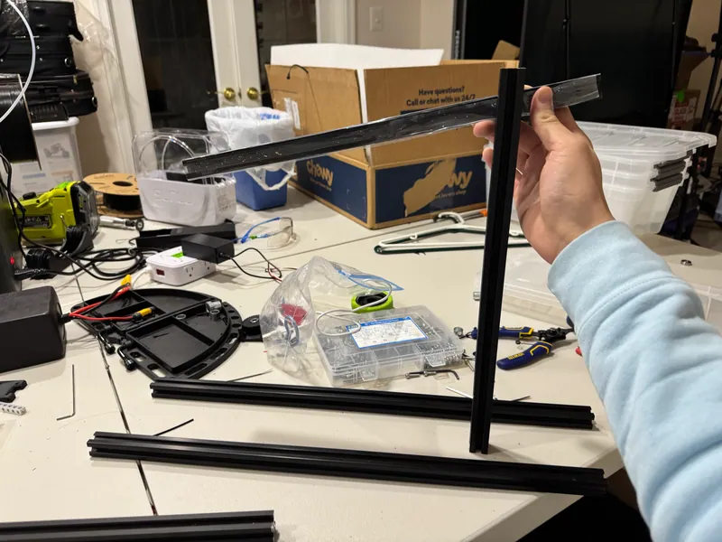
First dry fit of a beam on a post 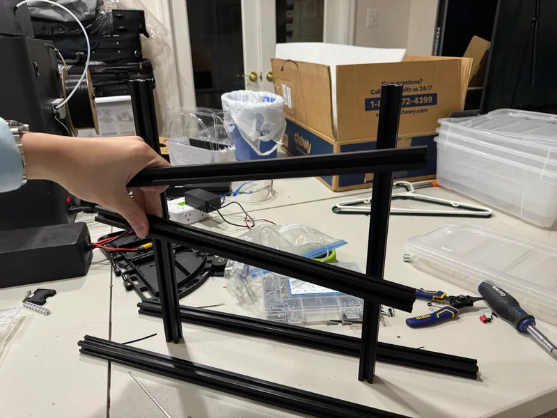
Both posts and a beam in the base Jan 16, 2026
Printed feet
The printed lattice foot plates on the two base rails, with the CAD open behind.
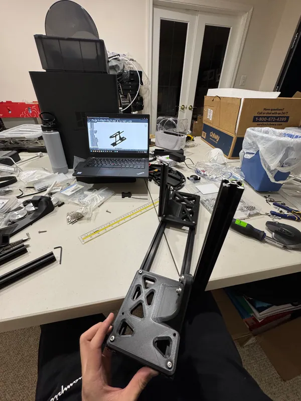
The base rails with a printed lattice foot plate Finished
Both levers and the link
Both levers on their bearings, the link, the printed rulers and the screw hangers, matching the CAD part for part.
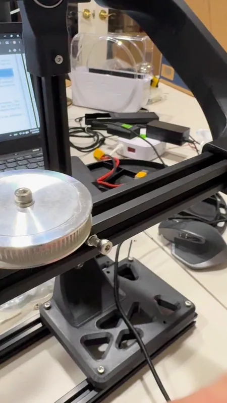
An aluminum pulley on the lower beam, with a screw hanger in the side slot 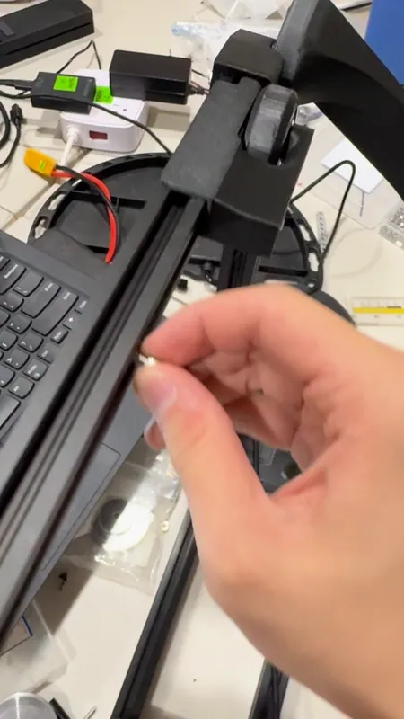
A screw hanger in the upper beam’s slot


