← All projectsMACROJul 2024
1 lb Combat Robot
Plastic antweight horizontal spinner
A 1 lb antweight combat robot designed and built in 4 days for MACRO's Ides of July event.
In four days I designed, printed and wired a 1 lb horizontal spinner and took it to my first combat robotics event, MACRO's Ides of July. The first version never left CAD: I ran a design review and redrew it thinner, with a one-piece TPU frame and an asymmetrical blade.
What knocked me out was electrical: a contact inside one of the N20 drive motors broke off because I had packed the wiring too tightly around it. I placed in the middle.
In the arena
My CAD of the finished robot in a small prop arena. As you scroll it spins the weapon up, drives in and hits three cardboard boxes, and the readout follows the blade.
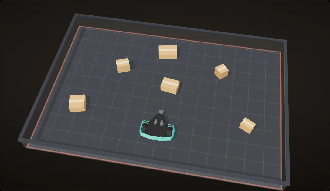
The robot and the arena
This is my CAD of the finished robot. The blade, the motor's bell and both wheels turn about their real axes from the STEP. The arena and the cardboard boxes are props for this page.
Spin up
The weapon comes up to its full no-load speed, 8,214 rpm. That is the same math as my weapon calculator: 740 rpm per volt times 11.1 V, with the blade bolted straight to the motor. On the 4.409 in (112 mm) blade the tip then moves at 158 ft/s (107.7 mph).
Drive in
It drives straight at the first box. The hit throws the box, takes speed off the blade, and the motor has to bring it back up.
Turn in place
Two wheels and tank steering: driving them in opposite directions turns the robot on the spot, so it can point the blade at the next box and go again.
And again
A third box. The readout shows the modelled blade speed at each moment: the drop on every hit, then the climb back toward 8,214 rpm.
The robot, blade and wheels are my CAD, turning about their real axes. The arena and the boxes are props, and the run is a simple physics model written for this page and worked out ahead of time, so the hits, the flips and the spin-up times are illustrative; the speeds come from my weapon calculator. The blade is drawn far slower than it really turns: 8,214 rpm is 137 turns a second.
The robot at a glance
A 1 lb (454 g) plastic antweight: a horizontal spinner on a two-wheel, tank-steered base.
| Part | What it is | Notes |
|---|---|---|
| Weapon motor | SunnySky V4006, 740 KV brushless outrunner | The blade bolts straight to the spinning bell: no belt, no gears |
| Blade | One tooth and a counterweight, 112 mm swing, 16 mm thick | Spins between the two plates |
| Drive | Two Pololu N20 gearmotors | Each one drives its wheel directly |
| Wheels | FingerTech foam wheels, 57 mm (2.25 in), on Twist hubs | Stand 10 mm past both plates |
| Frame | One TPU part, 196 x 103 x 37 mm | Wraps the whole robot |
| Plates | Two printed plates, 174 x 151 mm | Four M4 bolts clamp the stack |
| Power | LiPo and a REV power switch | ON and OFF printed into the frame |


The weapon
Direct drive
The blade bolts straight to the face of the SunnySky V4006's spinning bell with four M3 x 6 mm button-head screws, so it turns at motor speed. I wrote the screw size on a photo while I was working out the stack.


How fast
A brushless motor's no-load speed is its KV times the voltage, and with no reduction the blade turns at that speed. I checked the numbers in a weapon calculator:
Calculation How fast is the tip?
| Weapon motor | 740 KV | SunnySky V4006; my weapon calculator |
|---|---|---|
| Battery | 11.1 V | my weapon calculator |
| Blade diameter | 4.409 in (112 mm) | the swing of both blades in my CAD |
| Reduction | none | the blade bolts to the bell |
- No-load speed: 740 KV x 11.1 V = 8,214 rpm, or 137 turns a second
- Tip path per turn: π x 0.112 m = 0.352 m
- Tip speed: 136.9 turns/s x 0.352 m = 48.2 m/s = 158 ft/s (107.7 mph)
With no load the tip moves at 158 ft/s, the same as my calculator.
These are no-load numbers; every hit takes speed off the blade and the motor has to bring it back up.
Between the plates

The motor between the plates
The motor sits between the two plates instead of hanging off one of them. Its stator bolts to the bottom plate with four M3 screws.
Cut through the spin axis
My CAD, cut through the weapon's spin axis. The top plate carries a 4 mm bore bearing on that axis, over the end of the motor shaft, with a small spacer in between.
What spins
The blade, the motor's bell and the four M3 x 6 mm button-head screws that hold the blade to the bell turn together, lit orange. The stator, the bearings and the plates stay still.
Spin up
With no reduction the blade turns at motor speed, up to 8,214 rpm with no load. At that speed the tip of the 112 mm blade moves at 158 ft/s.
Section through the weapon axis of my CAD. The readout uses my calculator's numbers; the spin-up is illustrative, and the blade is drawn far slower than it really turns.
Two versions in four days
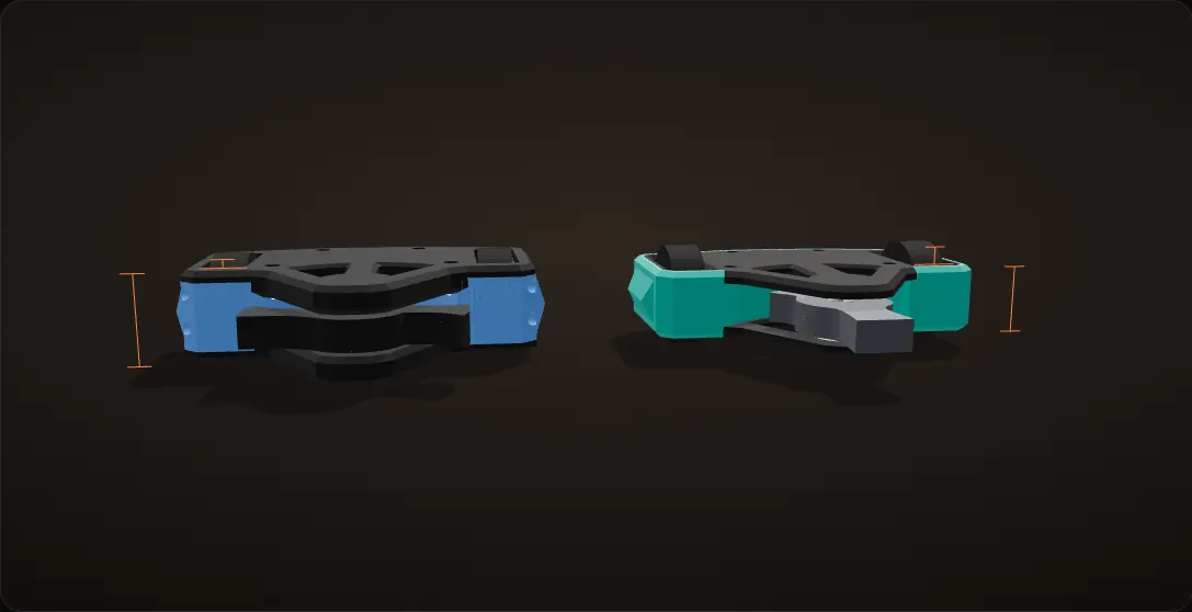
Both versions of my CAD at the same scale: version 1 in the blue of my own render, version 2 in the colours it was printed in.
Thinner
Version 2 drops the plates into the frame instead of stacking them on it. With the same 57 mm wheels, plate to plate goes from 48.0 mm to 37.2 mm, and the wheels now stand 10 mm past both plates instead of 4.6 mm.
One frame part
The TPU frame is a single print that wraps the whole robot. It replaces version 1's centre frame, both wheel guards, both motor clamps and the eight 35 mm bolts that held the guards on. The drive motors now sit in cradles printed into the bottom plate.
Asymmetrical blade
I made the weapon asymmetrical to increase its moment of inertia: one long tooth, balanced by a wide fan-shaped counterweight on the other side, in place of two teeth. It is 16 mm thick instead of 18 and sweeps the same 112 mm circle, and its centre of mass sits on the spin axis (from the CAD), so it runs balanced with one tooth.
A power switch
Version 2 adds a REV power switch at the back of the frame.
Dimensions and part counts measured on my two STEP files.
Problem Version 1 was thick
Version 1 was thick: 48.0 mm from plate to plate, with the plates stacked on top of and under a frame made of five parts, and a symmetrical two-tooth blade. I never built it.
Fix
I ran a design review and came out of it with a list of things I could improve, then redrew the robot. Version 2 is 10.8 mm thinner, its frame is one TPU part, and I made the blade asymmetrical to increase its moment of inertia.
| Version 1 (CAD only) | Version 2 (built) | |
|---|---|---|
| Plate to plate | 48.0 mm | 37.2 mm |
| Wheels past each plate | 4.6 mm | 10.0 mm |
| Plates | 184 x 157 mm, stacked on the frame | 174 x 151 mm, set into the frame |
| Frame | Centre frame, 2 wheel guards, 2 motor clamps | 1 TPU part |
| Fasteners | 22 screws, 14 nuts | 12 screws, 4 nuts |
| Blade | Two teeth, 18 mm thick | One tooth and a counterweight, 16 mm thick |
| Blade swing | 112 mm | 112 mm |
| Power switch | None | REV switch at the back |

Calculation How much energy does the blade store?
| Blade volume | 38.6 cm³ | measured from my CAD (the one-tooth blade) |
|---|---|---|
| Radius of gyration about the spin axis | 34.4 mm | measured from my CAD |
| Density, if printed solid in PLA | 1.24 g/cm³ | Prusament PLA datasheet; the material is assumed |
| No-load speed | 8,214 rpm | my weapon calculator |
- Mass: 38.6 cm³ x 1.24 g/cm³ = 48 g
- Moment of inertia: I = m k² = 0.048 kg x (0.0344 m)² = 5.7 x 10⁻⁵ kg·m²
- Spin: ω = 8,214 rpm x 2π / 60 = 860 rad/s
- Energy: E = ½ I ω² = ½ x 5.7 x 10⁻⁵ x 860² = about 21 J
About 21 J at full speed. The stored energy grows in step with the moment of inertia, which is what the asymmetrical blade was drawn to increase, and with the square of the speed.
Estimate: the blade alone, as if printed solid in PLA; its real material and infill are not recorded, and infill lowers it. The motor's spinning bell adds some, and every hit takes speed off.


Frame and drive
One flexible frame
The frame is a single print in TPU, a flexible filament, and it wraps the whole robot. The printed plates close it top and bottom and four M4 bolts clamp the stack together. ON and OFF are printed into the back of it, beside the holes for the switch.
Tank drive
Two Pololu N20 gearmotors sit in cradles printed into the bottom plate, and each one drives a 57 mm FingerTech foam wheel through a Twist hub on its output shaft. The robot steers like a tank.
Either way up
The wheels stand 10 mm past the top plate and 10 mm past the bottom plate, and the blade's mid-plane sits 1 mm below the axle line. So whichever side it lands on, the wheels still reach the floor and the blade stays within 2 mm of the same height (from the CAD).
Packing it
Everything else lives in the space between the wheels: the LiPo, the ESCs and all of the wiring. That packing is what failed at the event.


Taking it apart
My CAD of the finished robot, taken apart one layer at a time, then put back together and turned over.
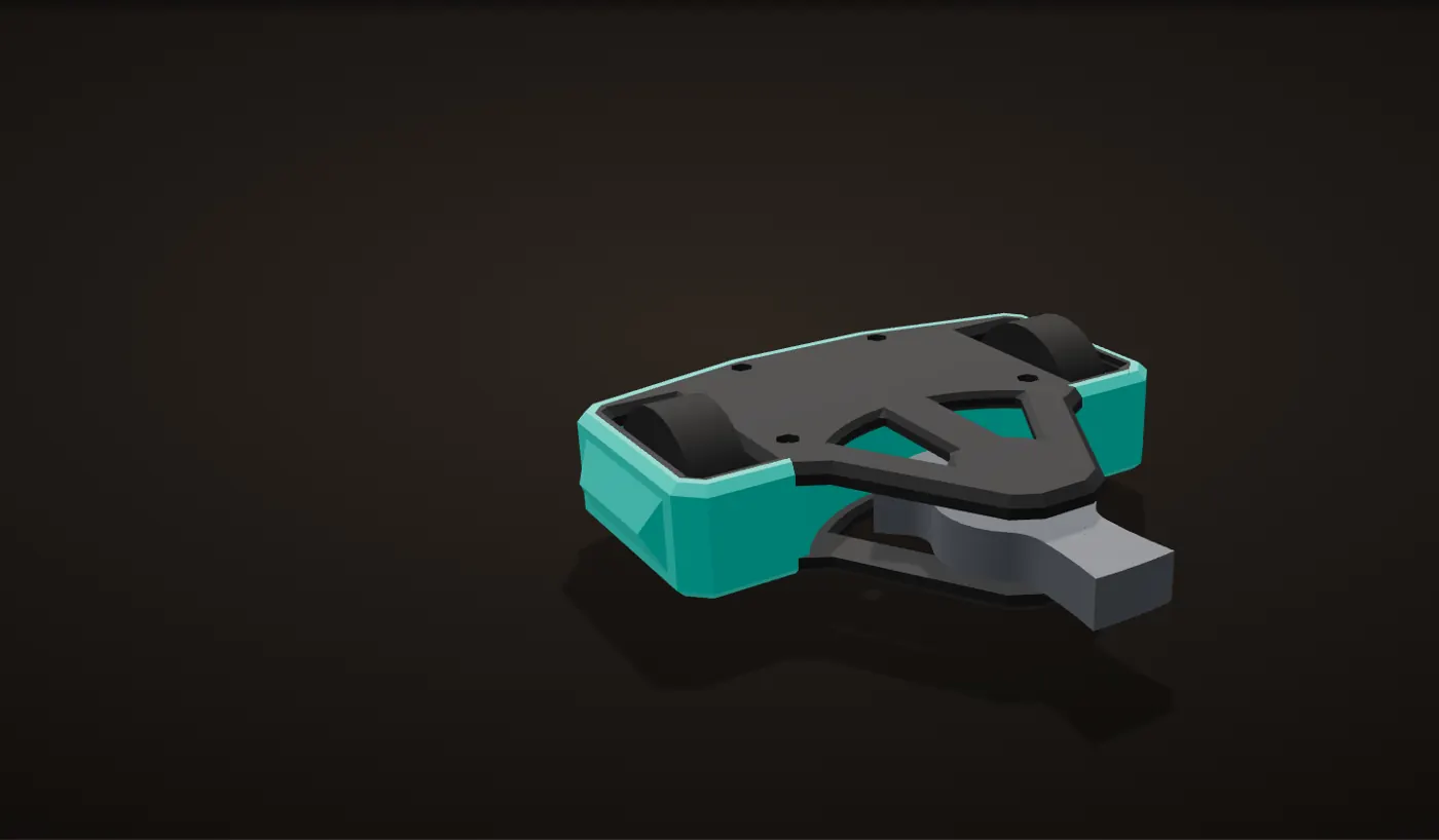
The finished robot
196 mm wide, 37.2 mm from plate to plate, and under a pound with the battery.
Top plate
It carries a 4 mm bore bearing on the weapon's spin axis, over the end of the motor shaft, with a small spacer under it.
Weapon
The blade bolts to the motor's spinning bell; the stator underneath it bolts to the bottom plate.
Drive
Two N20 gearmotors, each driving a 57 mm foam wheel on its own shaft. They slide out along the axle line.
Switch
A REV power switch at the back, reached through the holes beside the printed ON and OFF.
Frame
One TPU part that wraps everything, with windows for the wheels.
Bottom plate
Cradles for the two drive motors, and the seat for the weapon stator.
Either way up
Back together and turned over about the axle height: the wheels still reach the floor, and the blade is within 2 mm of the same height.
Four days
Jul 8 to 10
Research, then version 1 in CAD
I looked up the event's weight classes, batteries and connectors. In the CAD, the first saved versions hold just the wheels and the N20 drive motors; the weapon motor, the plates and the blade came next.
Jul 10
Design review, first prints, first spin
I ran a design review on version 1 and redrew the robot. That evening I printed the first blade and a plate, bolted the weapon on and spun it up inside a cardboard box.
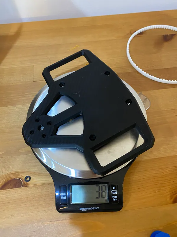
A printed plate on the scale: 38 g 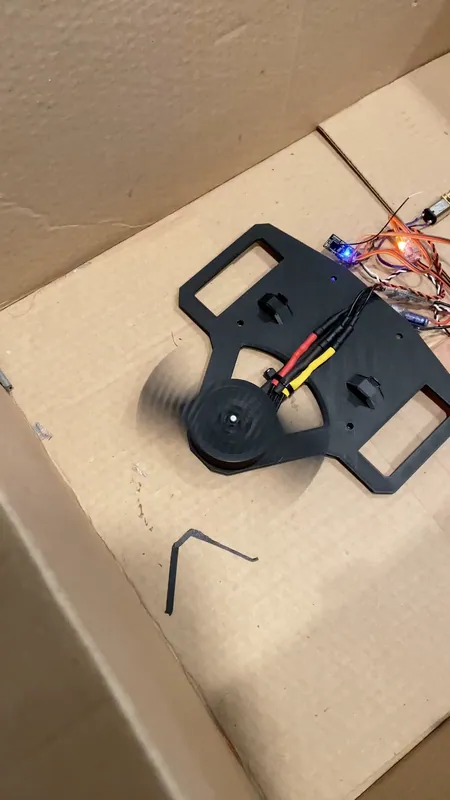
The spin test rig: plate, motor, blade and ESCs, in a cardboard box Jul 11
Frame, wiring, first drive
I printed the TPU frame, packed the electronics, closed it up, and drove it on a foam mat and on the table.
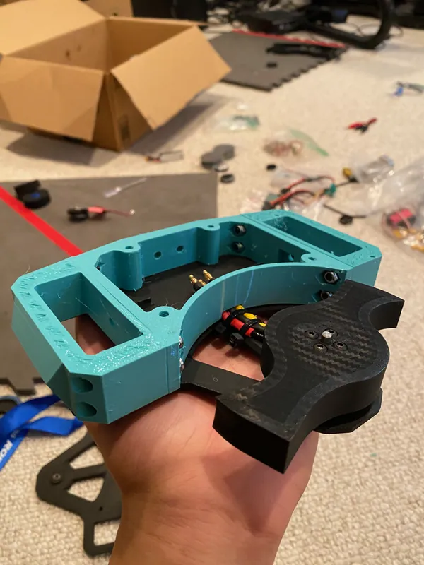
First test fit of the TPU frame on a plate, with the two-tooth blade The first drive test, on a foam mat Jul 12
New blade, rewiring
The one-tooth blade shows up in my photos. That evening and into the night I rewired the electronics.
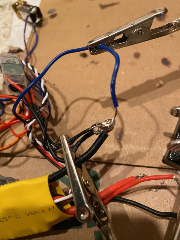
Rewiring with helping hands 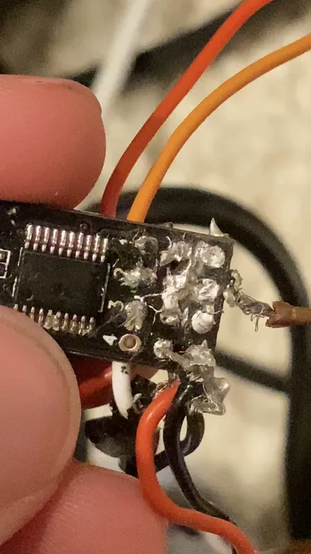
Leads soldered straight onto a board's pads, after midnight Jul 13, 2 AM
Weigh-in
439 g on my scale with the battery sitting on top: 14 g under the 454 g (1 lb) limit.
Calculation How much room was left?
On my scale, battery included 15.5 oz = 439 g the weigh-in photo (the scale reads ounces) Class limit 1 lb = 454 g the plastic antweight class One printed plate on the same scale 38 g my photo, Jul 10 - 15.5 oz x 28.35 g/oz = 439 g
- 454 g - 439 g = 14 g to spare
- 14 g / 454 g = 3 % of the limit, a bit over a third of one printed plate
The robot came in 14 g, 3 %, under the limit.
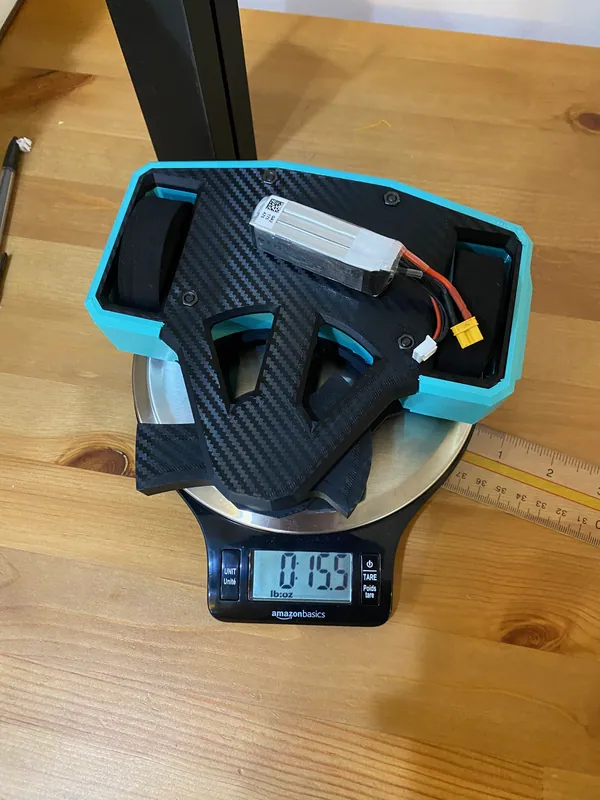
The scale reads 0 lb 15.5 oz (439 g) with the LiPo on top


Ides of July
MACRO, the Maryland Area Combat Robotics Organization, ran Ides of July in Severn, Maryland on July 13, 2024. My robot fought in the plastic antweight class.
Problem A contact broke inside a drive motor
My robot was knocked out by its electronics. The Pololu N20 drive motors have small tabs on the back for their leads, and I had packed all of the wiring into the frame tightly around them. A contact broke off inside one of the motors.
I placed in the middle, at my first event, with a robot designed and built in four days.


CAD history
The whole design history is public on GitHub at github.com/jerryli08/antweight: Fusion files and STEP exports for 19 saved versions of the robot (v2 to v37) and two versions of the asymmetrical blade test, with a README listing the motors and wheels. There is no code in it; it is the CAD.
Opened in order, the versions show how the robot came together: the wheels and drive motors first (v3, v4), then the weapon motor (v8), the plates (v10), the first blade and the wheel guards (v12), the bolts and the top bearing (v14, v15), the power switch (v27), the asymmetrical blade (v31), and finally the one-piece TPU frame that replaced the guards and clamps (v37).