← All projectsMonkeytypeMay to Jun 2025
Monkeytype Shirt
A shirt I designed for Monkeytype, sold on their official store: the print is an exploded view of a servo-driven mechanism I designed in CAD.
I designed the Deconstructed T-Shirt on the official Monkeytype store. The print is an exploded view of a small machine I designed in CAD, whose whole job is to push a keycap on a keyboard switch all the way in.
One servo drives a bevel gear pair, a belt, a spur gear pair and a crank linkage that runs a carriage along a miniature linear rail. I made it far more complex than the job needs, on purpose, so the drawing has more to look at.
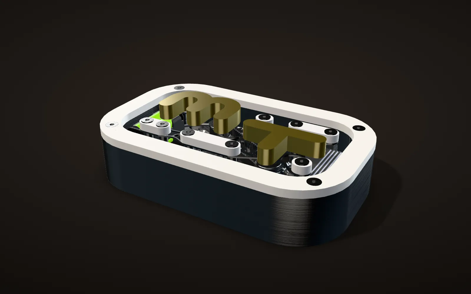
Closed
The machine closed up as one box: a tub, a white lid ring and the Monkeytype "mt" logo on top. Everything that moves is inside.
Opening
The four corner screws back out along their guide lines, then the logo, the top frame and the lid ring lift off, like a step in an assembly manual.
The mechanism
Every stage rises to its own height so nothing hides behind anything else: the servo, the bevel gears, the belt, the spur gears, the linkage and the rail all show at once.
This is the shirt
This exact pose, seen from this angle, is the drawing on the shirt.
My CAD, exported in its exploded pose. The closed box is the same parts with each layer lowered straight back down, along the explode axis, onto the part it mounts to.


One keycap, five stages
The machine has one job: push a keycap on a keyboard switch all the way in, and let it back out. Instead of doing that directly, I sent the servo's motion through a chain of different mechanisms, on purpose, for visual interest. Each one is one more thing to look at in the drawing. Here it runs in the exploded pose from the shirt, with the lid and the top frame lifted away.
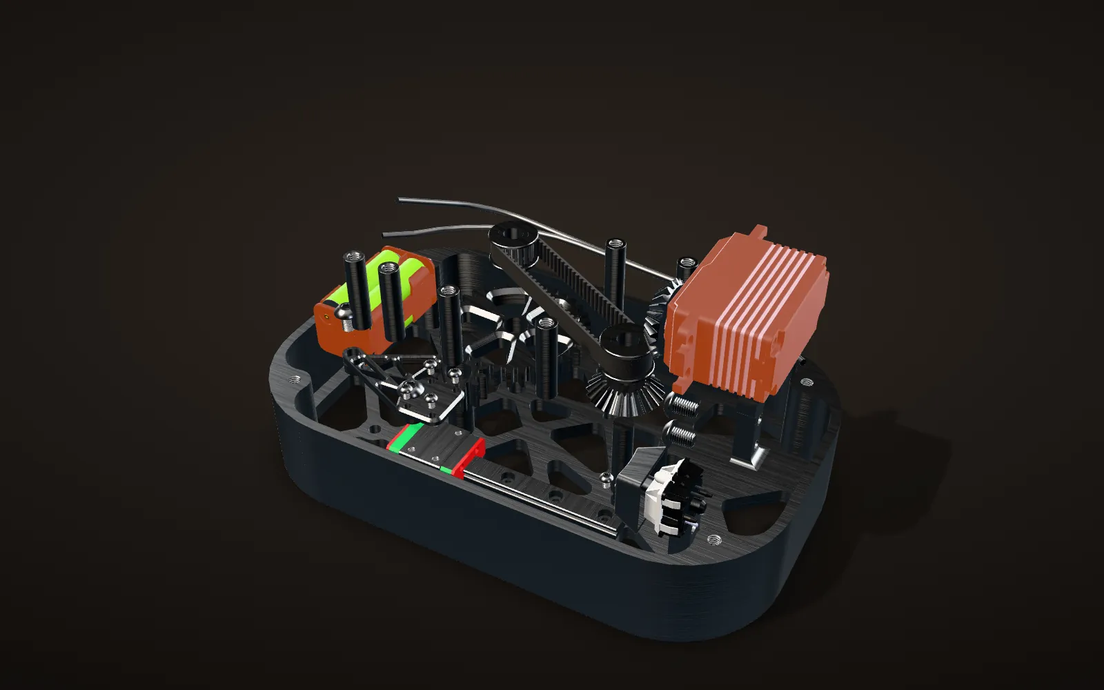
1. The servo
An Axon Max Plus servo is the only actuator, wired to a 4xAA battery holder at the other end of the box. Its output shaft lies flat, pointing along the box.
In every step the servo makes one push and comes back, so each stage can be watched doing its part.
2. Bevel gears
Two identical bevel gears turn the servo's horizontal shaft into a vertical one at 1 : 1. From here on, every shaft stands straight up from the floor of the box.
In the exploded pose the pair is drawn apart along the explode axis like every other layer, so here they turn without touching.
3. Belt
A 20-tooth pulley on the bevel shaft drives a second 20-tooth pulley 60 mm away through an 80-tooth belt with a 2 mm pitch. Equal pulleys, so it is still 1 : 1: the belt is there to carry the motion across the box.
One push turns both pulleys 38.8 degrees, which moves the belt 4.3 mm around its loop, just over two teeth.
4. Spur gears
The second pulley shares its shaft with a 36-tooth gear, which drives a 12-tooth gear, module 1.25, with their centres 30 mm apart. That is a 3 : 1 step-up: the 12-tooth gear turns the opposite way to the 36-tooth gear and three times as far, so three times as far as the servo.
5. Crank
The 12-tooth gear carries a 32 mm crank arm. A 33 mm link joins the crank to the carriage and turns the crank's rotation into a straight push.
The crank axis sits 24 mm off the line of the rail, so this is an offset slider-crank. The 116 degrees the crank turns in one push move the carriage 55.9 mm.
6. Linear rail
The carriage rides a 70 mm MGN7 miniature linear guide, so the push stays straight. The push starts with the block at the back end of the rail and runs it 55.9 mm, until the plate on the block has pressed the keycap all the way in.
7. The keycap
The whole chain is there for this: a keycap on a Cherry MX switch, lying on its side at the end of the rail. The plate on the block meets the keycap 33 mm past where the CAD has the carriage, pushes it the switch's full 4 mm of travel to the bottom, then backs off and lets the key spring back out.
Tooth counts, centre distances, link lengths and the 33 mm from the plate to the keycap are measured from my CAD. One push here is 38.8 degrees at the servo: through the 3 : 1 spur stage that is 116 degrees at the crank, which runs the carriage 55.9 mm, from the back end of its rail to the bottom of the key's travel. The switch in the CAD is a simplified model with no working stop, so the press uses Cherry's published 4 mm of total travel.
What is in the box
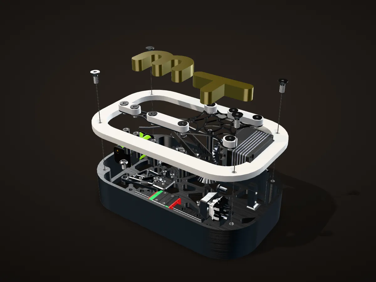
The whole machine
My CAD as exported, in the pose on the shirt. The mechanism sits in a stadium-shaped tub, 163 by 101 mm, and every layer above it is lifted straight up.
The frame
Six 24 mm hex standoffs stand on the tub floor. On top of them a 1 mm web plate ties the eight top screw points together, clamped under 5 mm bars by eight countersunk M4 screws.
The lid and the logo
A white lid ring sits on the tub rim, and the Monkeytype "mt" logo, 10 mm thick, sits on the web plate between the bars.
Four more countersunk screws go through the lid ring into the corners of the tub. In the exploded CAD each one floats above its hole on a thin guide line, the way an assembly drawing shows where a screw goes.
The parts
Power goes one way through the box: servo, bevel pair, vertical shaft, first pulley, belt, second pulley, 36-tooth gear, 12-tooth gear with its crank, link, carriage on the rail, and finally the keycap.
| Stage | Parts in the CAD | From the CAD |
|---|---|---|
| Power | Axon Max Plus servo, 4xAA battery holder, two wires | Output shaft horizontal, along the box |
| Bevel | Two identical bevel gears | 1 : 1, turns the motion 90 degrees |
| Belt | Two 20-tooth pulleys, an 80-tooth belt | 2 mm pitch, 60 mm between centres, 1 : 1 |
| Spur | 36-tooth and 12-tooth gears | Module 1.25, 30 mm between centres, 3 : 1 step-up |
| Linkage | Crank arm on the 12-tooth gear, a link to the carriage | 32 mm crank, 33 mm link, 24 mm offset |
| Rail | MGN7 rail and block, a carriage plate | 70 mm rail |
| Output | Cherry MX switch and keycap | Switch on its side, facing the carriage |
| Housing | Tub, lid ring, six standoffs, web plate, top bars, the "mt" logo, 12 countersunk M4 screws | Tub 163 x 101 mm, standoffs 24 mm |
Calculation Does the 80-tooth belt fit two 20-tooth pulleys 60 mm apart?
| Pulleys | 20 teeth each, 2 mm pitch | measured from the CAD |
|---|---|---|
| Distance between the pulley axes | 60 mm | measured from the CAD |
| Belt | 80 teeth, 2 mm pitch | measured from the CAD |
- Pitch diameter of each pulley: 20 × 2 mm / π = 12.73 mm
- Equal pulleys, so the belt is two straight runs plus half a wrap round each: L = 2 × 60 mm + π × 12.73 mm = 120 mm + 40 mm = 160 mm
- In teeth: 160 mm / 2 mm = 80
Exactly 80 teeth: the 60 mm between the pulley axes is the distance an 80-tooth, 2 mm pitch belt needs.
Lengths along the belt's pitch line.

Calculation Why 30 mm between the spur gears, and what 3 : 1 does
| Gears | 36 and 12 teeth, module 1.25 | measured from the CAD |
|---|---|---|
| Crank turn for one push, from the back end of the rail to the bottom of the key's travel | 116.4 degrees | the linkage below, measured from the CAD |
- Pitch diameters: 1.25 × 36 = 45 mm and 1.25 × 12 = 15 mm
- Meshing distance: (45 mm + 15 mm) / 2 = 30 mm, the distance between the two gear axes in the CAD
- Ratio: 36 / 12 = 3, so the 12-tooth gear and its crank turn 3 degrees for every degree of the 36-tooth gear, which turns with the servo (1 : 1 through the bevels and the belt)
- Servo turn for one push: 116.4 / 3 = 38.8 degrees
Module 1.25 gears with 36 and 12 teeth mesh at exactly 30 mm, and the 3 : 1 step-up lets 38.8 degrees at the servo swing the crank the 116 degrees one push needs.
Pitch circles; the backlash allowance in the CAD, if any, is left out.
Calculation Can the crank push the key all the way in?
| Crank, link, and the crank axis's offset from the rail line | 32.0 mm, 33.1 mm, 24.0 mm | measured from the CAD |
|---|---|---|
| Carriage pin ahead of the crank axis, in the CAD pose | 19.0 mm | measured from the CAD |
| Plate on the block to the keycap's top face, in the CAD pose | 33.0 mm | measured from the CAD |
| Cherry MX total travel | 4 mm | Cherry |
- Carriage pin ahead of the crank axis with the key at the bottom: 19.0 + 33.0 + 4 = 56.0 mm
- Furthest the pin can get, with crank and link in line: √((32.0 + 33.1)² − 24.0²) = √(4238 − 576) = 60.5 mm
- Crank angle at the bottom of the press: −44.0 degrees; in line (the dead point): −21.6 degrees
- Link angle to the rail at the bottom: about 3 degrees
The press bottoms out 4.5 mm short of the linkage's dead point, with 22 degrees of crank to spare, and at the bottom the link pushes almost straight along the rail.
Geometry only; crank angles from STEP +X about the 12-tooth axis.
From CAD to a shirt
The drawing on the shirt is the CAD itself: the same parts in the same exploded pose, seen from the front left and above. In the CAD every layer is lifted to its own height and the corner screws have guide lines down to their holes, so the whole mechanism reads in one white line drawing.

