← All projectsFIRST Tech ChallengeMar 2024
Horizontal Extension Intake for Cryptic
FTC CENTERSTAGE, 2023-24
A horizontal extension intake I designed for team Cryptic after they advanced to Worlds.

After my FTC season ended and team Cryptic advanced to the World Championship, I proposed a horizontal extension intake for their robot, since it was a clear advantage that year, and designed it.
Three slides on each side, opening one after another, push the intake about a metre out in front of the robot. Its front rollers fold down to the tiles, star rollers and a counter roller pull pixels up a ramp, and when the slides pull it back in, the ramp lines up with the robot's 4-bar dumper for the handoff. It stayed a concept: with Worlds coming up fast, it added too much risk for the reward.
One intake cycle
The real CAD, moved by your scroll. The slides, the fold-down arm and every roller move along or about their own axes in the model.
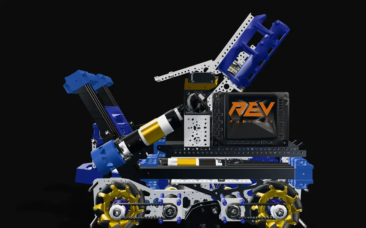
Stowed
From the side, with the outer drive plate hidden: each side has three slides of three 300 mm bodies each. Stowed, all nine sit in line, front and back, inside the robot.
Extend
The slides open one after another: the first by 160.6 mm, the next two by 400 mm each. That carries the intake 960.6 mm, about a metre past the front of the drivetrain.
Fold down
The three front star rollers ride on a 114 mm arm that pivots on the intake's main hex shaft. The arm folds down, bringing them down to the tiles.
Roll in
The star rollers sweep the pixels back. The counter roller at the lip of the ramp turns the other way and lifts each one onto the ramp, and they ride up until the first sits on top, under the rear rollers.
Fold up
The arm folds back up with both pixels on board.
Retract
The slides close up again, all nine bodies on each side back in line inside the robot, and the intake sits between the two sides of the drivetrain.
Transfer
Pulled in, the top of the ramp sits just in front of the robot's 4-bar dumper, on the same centreline and at about the same width. The rollers push the pixels off the back of the ramp and into the dumper.
Seen from the side with the outer drive plate hidden, then cut through the ramp (cut faces are hatched). The pixels are added to show the path; they are not part of the CAD. The rollers are slowed down, and their speeds are not from the CAD, which does not include the motors and servos that would drive the slides, the rollers and the fold.
Why an extension intake
In CENTERSTAGE, the 2023-24 FTC game, robots pick up pixels, flat hexagons 3 in across and half an inch thick, and score them on a backdrop.
An intake on horizontal slides reaches out for pixels while the robot stays where it is, then pulls them back inside in one motion. I thought that was a clear advantage that season, so after my own season ended and Cryptic advanced to Worlds, I proposed one for their robot and designed it.
It was never built, so every picture on this page is my CAD. The CAD holds the whole robot with the intake built in; the intake and its slides are my design. The pixels in the animations are added to show their path and are not part of the CAD.

How the intake works
Slides and frame
The intake rides on six Misumi SAR330 slides, three on each side of the robot, and every slide is three 300 mm bodies: an outer, a middle and an inner one. On each side the first slide's outer body stays with the robot, against the outer drive plate. Its inner body is joined back to back to the second slide's outer body by two V-groove blocks, the second slide's inner body to the third's outer body the same way, and the third slide's inner body carries the intake. The intake is built between two triangular side plates that hang from those inner bodies to just above the tiles, with two 1.5 in omni wheels under it, a few millimetres off them.

Calculation How far do the slides carry the intake?
| Slides on each side | 3, bolted in a row | from the CAD |
|---|---|---|
| Bodies in each slide | 3, each 300.0 mm long | measured from the CAD |
| First slide, fully out as modelled | inner body 160.6 mm out | measured from the CAD |
| Second and third slides | middle 200 mm past outer, inner 200 mm past middle | measured from the CAD |
| Stowed | all nine bodies in line, front and back | Jerry |
- Intake travel = 160.6 + (200 + 200) + (200 + 200) = 960.6 mm
- Stowed, a side packs into one body length, 300 mm, while the robot is 455 mm from front to back (measured from the CAD)
- Fully out, each body of the second and third slides still overlaps the one it rides on by 300 − 200 = 100 mm
- The front rollers then sit 999 mm past the front of the drivetrain (measured from the CAD)
Nine 300 mm bodies on each side give 0.96 m of travel, and stowed they all sit inside the robot: front ends about 2 mm behind its front, back ends about 150 mm ahead of its back.
Measured along the slide axis on the levelled CAD. The CAD has no motor or string for the slides, so there is no speed to work out.

Rollers
Three TPU star rollers, 103 mm across, sit on the intake's 312 mm hex shaft, and three more on a front shaft that the fold-down arm carries 114 mm ahead of it. Both shafts carry the same sprocket on one side, for a chain between them (the chain is not in the CAD), so the front and middle rollers turn together.
Behind them, two 60 mm TPU rollers sit over the flat top of the ramp. Their tips come within about 10 mm of it, less than a pixel's 12.7 mm, so a pixel on top is pinched between them and the ramp.

Problem Getting a flat pixel off the tiles
A pixel is a flat hexagon, only 12.7 mm thick, lying on the tiles, and the intake has to lift it about 70 mm to the top of its ramp.
Fix
The front star rollers are on an arm that folds down, so they come down to a pixel on the tiles and sweep it back. At the lip of the ramp a 16 mm counter roller, turning the other way, lifts the pixel's edge onto the ramp, and the middle star rollers carry it up to the rear rollers.
The counter roller drive
A 40-tooth servo gear drives the counter roller through a 15-tooth gear on its shaft, so the roller spins 2.67 times as fast as the servo (40 / 15). The two gears sit 22.0 mm apart, exactly right for module 0.8 gears.
Calculation Do the counter roller gears mesh?
| Servo gear (goBILDA 2305-0025-0040) | 40 teeth, module 0.8 | part number in the CAD; goBILDA |
|---|---|---|
| Gear on the counter roller | 15 teeth | counted in the CAD |
| Shaft centres apart | 22.0 mm | measured from the CAD |
- Speed: 40 / 15 = 2.67 turns of the counter roller for every turn of the servo
- Centre distance for a module 0.8 pair: 0.8 × (40 + 15) / 2 = 22.0 mm
The spacing in the CAD is exactly the centre distance of a module 0.8 pair, so the two gears mesh as modelled, and the counter roller runs 2.67 times as fast as the servo.

Spur gears: centre distance = module × (teeth on both gears) / 2.
Problem The handoff
Once the intake is back inside the robot, the pixels still have to get from the intake into the outtake.
Fix
Pulled in, the top of the ramp sits just in front of the robot's 4-bar dumper, on the same centreline, at the same width (102 mm for the ramp, 106 mm for the dumper's tray) and about 25 mm above the tray's front edge. The rollers push the pixels off the back of the ramp straight into the dumper.
Every dimension here is measured on the CAD: roller sizes from their meshes, the gear spacing between the shaft centres, the ramp and tray widths and heights with the model levelled on its wheels.

The design in CAD
My CAD, turned by your scroll.
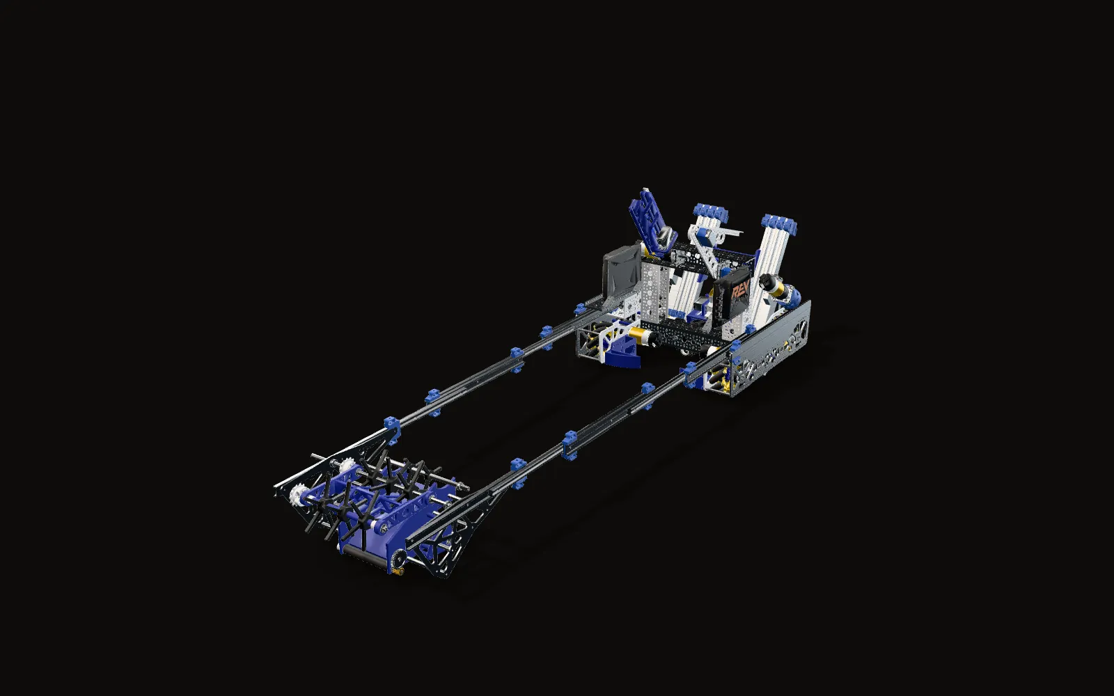
The whole robot
The intake fully out on its slides. Behind it is the rest of the robot in the file: a mecanum drivetrain, an angled lift and the 4-bar dumper that the intake feeds.
Rollers and ramp
Six star rollers in two rows over a ramp one pixel wide, with the counter roller at the ramp's lip.
The chain side
The same sprocket on the main shaft and on the front shaft of the fold-down arm, for a chain between them, so both rows of star rollers turn together.
The gear side
On the other side, cut just inside the ramp's side wall: the 40-tooth servo gear drives the 15-tooth gear on the counter roller's shaft.
Cut faces are hatched. Screws, nuts and e-clips are left out, and so are seven stray copies of robot parts that sat inside the intake's component in the file. Every other part is the CAD as modelled.
It remained a concept
Cryptic did not use it. The Worlds deadline was coming up fast, and a new intake added too much risk for the reward, so they put their time into other parts of their robot, mainly its reliability.