← All projectsHoward County Library SystemJul to Aug 2024
FTC CENTERSTAGE Offseason Robot
Telescoping pitching arm
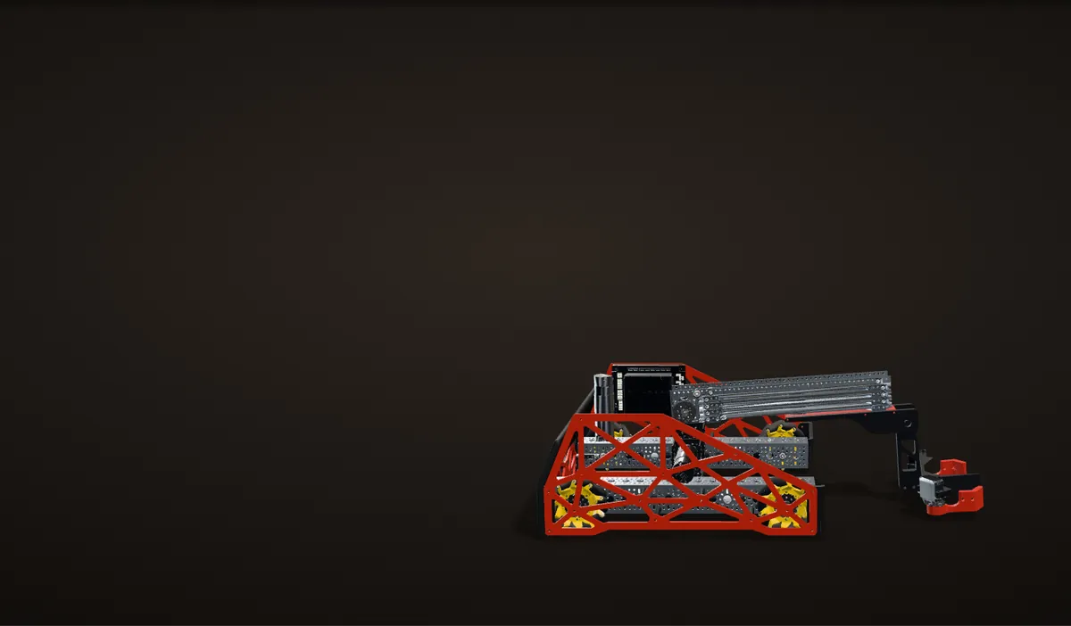
An FTC CENTERSTAGE robot with a pitching claw on four-stage belt-driven slides, built in less than a week to demo at the library system's STEAM Carnival.
For my internship with the Howard County Library System, I was tasked with building an eye-catching FIRST Tech Challenge robot to demo at the STEAM Carnival the library system hosts, to recruit for the library system's FTC class, which I taught. Inspired by the FTC team KookyBotz, I designed a pitching claw robot for the CENTERSTAGE game: four-stage belt-driven Viper-Slides on a pivot, so one mechanism reaches out along the floor to grab two pixels, then swings up over the back of the robot to score them. I had less than a week for everything, so I used as many off-the-shelf goBILDA parts as I could.
It ran at the carnival on Aug 3, 2024, where visitors from the community, children and adults, drove it. Two things broke. The low-side U-channel that carries the slides cracked just past the pivot and then snapped, after the arm had pivoted several times with the slides all the way out; my FEA of it is below. And in the weeks after the demo, a student picked the robot up by one of the laser-cut acrylic sideplates and broke it. The code is on GitHub.
One full cycle
Scroll to run one cycle on my real CAD, in the order the robot works: reach out, grab two pixels, pull in, pitch over the back, reach again and drop them on the backdrop.
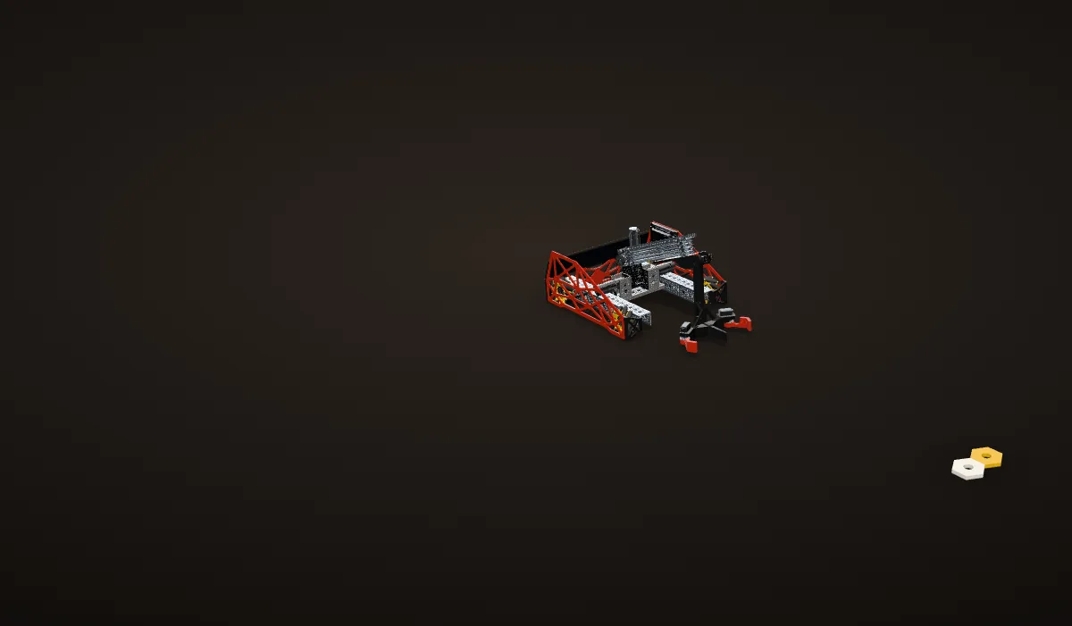
1. Stowed
Slides in, the arm tilted up so the claw hangs clear of the floor. Two pixels wait where the claw lands at full reach.
2. Reach
One 435 rpm motor drives a single belt through all four slide stages at once: 245 mm each, 979 mm in all (from my CAD).
3. Grab
Each finger has its own servo and its own bumper on the second gamepad; the right trigger moves both. Two pixels, side by side.
4. Pull in
The slides come back in with both pixels before the arm swings up; it only tilts enough to keep the claw off the floor. The code never enforced that order: see what broke.
5. Pitch
Two 43 rpm motors swing the arm over the back to 120 degrees from flat, until the slides are parallel to the backdrop's 60 degree face. The wrist turns the claw over, so the pixels face the backdrop.
6. Reach again
The slides run out along the face, still parallel to it, and the wrist lays the pixels flat on it: the claw rests right against the face without overlapping it.
7. Drop
The fingers open and both pixels slide down the face into the two middle notches of the bottom row. Then slides in, arm down, and the next pair.
My real CAD, rigged about its real axes: the arm turns about the line through both pivot motor shafts, the four slide stages run along the arm (each ball carriage at half its stage's speed, as in a real Viper-Slide), and the wrist and each finger turn about their servo output splines. The pixels and the floor are added for the animation. The backdrop is the official CENTERSTAGE backdrop from the field CAD (AndyMark am-5103), its bottom edge against the robot's back; in step 6 a cut through the middle of the claw shows the claw and a held pixel touching its face. The claw is drawn 100 mm longer than in my CAD (the stem between the wrist and the fingers is stretched), because my CAD is likely an older version than the robot I built: at that length the claw touches the face with the slides parallel to it, and nothing overlaps the backdrop. The CAD has the belt only fully in and fully out, so it is hidden while the slides move.
The brief
The Howard County Library System hosts a STEAM Carnival, and as part of my internship there as a STEM instructor and youth peer intern, I was tasked with making an eye-catching FIRST Tech Challenge robot to demo at it, to recruit for the library system's FTC class. I had less than a week for everything, so the plan was to use as many commercial off-the-shelf parts as possible and design only what I had to.
The game was CENTERSTAGE, the 2023-24 FTC game: robots pick up hexagonal pixels and place them on the backdrop, a slanted board. I started from an older goBILDA robot, a Strafer chassis with cable-driven Viper-Slides, a claw and a wrist, took it apart and rebuilt it around a pitching arm, inspired by the FTC team KookyBotz. The slides rotate for horizontal extension and for height, so one mechanism reaches out across the floor for pixels and also lifts them to the backdrop. The claw in my CAD is still called "kooky claw v2".
Problem No dual blocks
The layout needed goBILDA dual blocks to put channels in the right places, and I did not have any.
Fix
I improvised the same positions from U-channels and quad blocks I had on hand.


How it works
My CAD of the finished robot, posed the way I designed it: arm flat, slides all the way out.
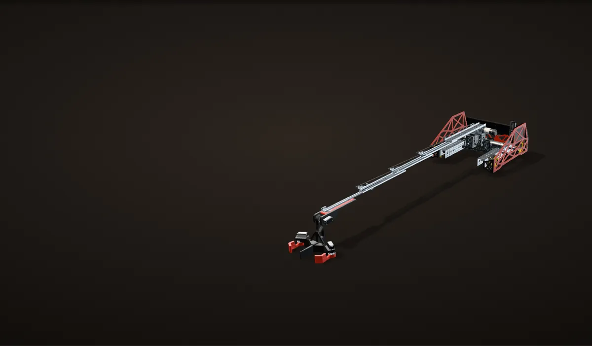
The whole robot
430 mm across the sideplates, 456 mm long with the bumpers (from my CAD). Arm, slides and claw all sit on one pivot in the middle; at full reach the claw tip is 1.49 m out from it.
Drive
A goBILDA Strafer chassis: four 312 rpm motors along the side channels, each turning a 96 mm mecanum wheel through 1:1 bevel gears. Free speed: 312 rpm × π × 96 mm = about 1.6 m/s.
The code is standard mecanum mixing, strafe scaled by 1.1 "to counteract imperfect strafing".
Pivot
Two 43 rpm motors face each other on one axis, 94 mm above the floor, each on its own 72 mm U-channel tower. Their hubs bolt to a third 72 mm U-channel; the slide kit's 1-hole U-channel and low-side U-channel stack on it and carry the slides. Direct drive, load shared.
Slides
A goBILDA belt-driven four-stage Viper-Slide kit, 336 mm slides. One 435 rpm motor at the base of the arm pulls one belt, and all four stages move together: 245 mm each, 979 mm in all. The motor pivots with the arm.
Claw and wrist
A servo at the end of the slides pitches the whole claw (the wrist). Two red fingers, each on its own servo, hold two pixels side by side. Printed body and mounts; a LEGO ball caster under it (not in the CAD).
Sideplates and back plate
Red acrylic truss sideplates, about 3 mm thick and 432 mm long, on eight printed 56 mm standoffs. The printed back plate spells HOWARD COUNTY LIBRARY SYSTEM in 25 red letters beside the library's logo.
The build, day by day
Jul 25
First layout in CAD
The first layout in Fusion 360: the slides reaching far out past a Strafer chassis, on a pivot in the middle of the robot.
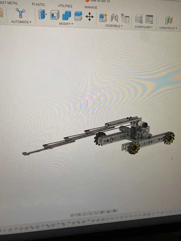
Jul 25: the first layout in Fusion 360, slides far out past the chassis Jul 29
Teardown and a new frame
I took the old robot apart and started the new frame from its parts. The drive stayed the Strafer's: four 312 rpm motors, each turning a 96 mm mecanum wheel through a pair of bevel gears.
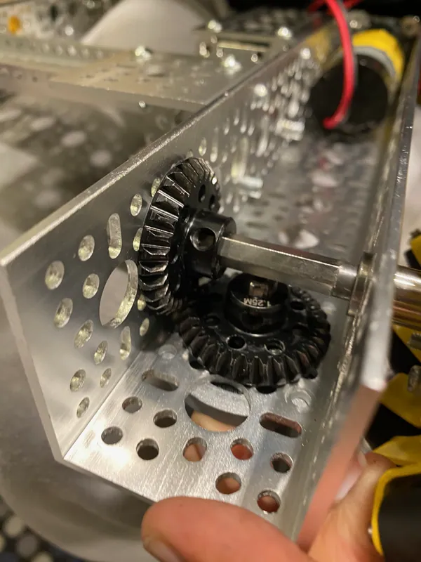
Jul 29: the bevel gears inside a drive channel of the Strafer chassis Jul 30
The slides go from cable to belt
I took the old cable-driven slides apart and converted them to belt drive: bearing idlers, end stops and pulleys on each stage, then the belt routed through them. That evening I rendered the whole robot in its red and black.
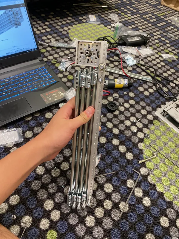
Jul 30: the four-stage slide assembled after the belt conversion 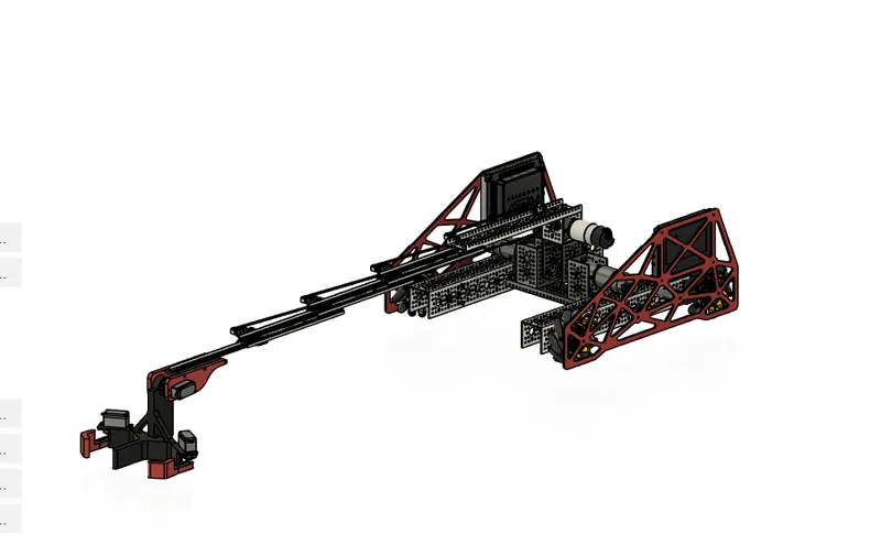
Jul 30: my render of the robot, slides out with the claw Jul 31
First motion, and a new pivot motor
I printed the wrist and claw parts at home in the morning, then ran the slides for the first time: straight up, then flat along the floor. The pivot needed as much torque as I could get, which meant as low a motor speed as possible, and at first I only had 312 rpm motors. That night at home I swapped in 223 rpm motors borrowed from a friend, with new D-bore hubs, and tested the pivot with the claw on.
Problem
One of the 223 rpm motors had a damaged JST-PH connector.
Fix
I soldered the motor's leads to a JST-PH connector and heat-shrank the joints.
Jul 31: the first extension test, slides straight up on the bare chassis Jul 31: the slides lying flat, running out across the tiles Jul 31, at home: the first pivot test with the printed wrist and claw Aug 1
Claw, final pivot motors, sideplates
The two-finger claw went on in the morning. The 43 rpm motors that had been ordered arrived, so the pivot changed motors a final time, with new 8 mm REX hubs, and I tuned its controller. In the afternoon I laser cut the truss sideplates from red acrylic, and that night I printed the letters and the logo for the back plate.
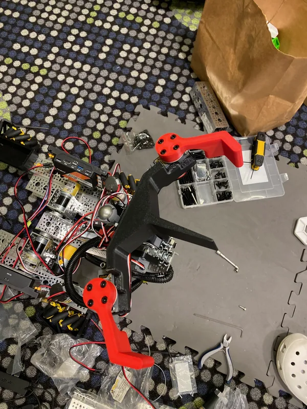
Aug 1: the two-pixel claw with its two red fingers Aug 1: the laser cutter tracing a truss sideplate in red acrylic Aug 2
Finished
Sideplates and the lettered back plate on, then drive tests with the finished robot.
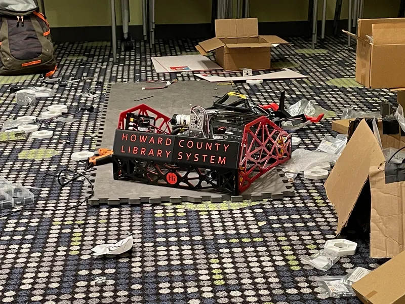
Aug 2: the finished robot, red truss sideplates and the lettered back plate


Holding a long arm steady
The pivot is the hard part of a pitching robot. Gravity pulls hardest on the arm when it lies flat and not at all when it stands straight up, and the slides make the arm longer or shorter on top of that. A plain proportional controller has to build up error before it pushes back, so the arm would sag below its target by an amount that changes with the angle.
So the pivot runs a proportional term plus a gravity feedforward term. The feedforward gives the motors the power gravity needs at the current angle, and the proportional term only has to close what is left:
angle      = -360 * position / 3895.9       (degrees)
gravity    = 0.18 * cos(angle + 110°)
pitchPower = -0.001 * (target - position) + gravity
The motors drive the arm directly, with no gears or belts between them and the arm, so their gearboxes set the torque. I needed as much torque as possible, which meant as low a speed as possible: I started with the 312 rpm motors I had, moved to 223 rpm motors borrowed from a friend, and ended on the 43 rpm motors that had been ordered.

Calculation Which pivot motors could hold the arm out?
| Gravity moment about the pivot, arm flat, slides in | 4.1 N·m | my CAD (masses and positions of every part on the arm) |
|---|---|---|
| The same, slides all the way out | 12.4 N·m | my CAD |
| Stall torque, 312 rpm motor | 24.3 kg·cm = 2.38 N·m | goBILDA 5203, 19.2:1 |
| Stall torque, 223 rpm motor | 38.0 kg·cm = 3.73 N·m | goBILDA 5203, 26.9:1 |
| Stall torque, 43 rpm motor | 185 kg·cm = 18.1 N·m | goBILDA 5203, 139:1 |
| Pivot motors | 2, direct drive | my CAD |
- 312 rpm pair: 2 × 2.38 = 4.8 N·m, barely above 4.1 with the slides in and well under 12.4 with them out
- 223 rpm pair: 2 × 3.73 = 7.5 N·m, 1.8 times the load with the slides in, still under 12.4
- 43 rpm pair: 2 × 18.1 = 36.3 N·m, 2.9 times the load with the slides out
Only the 43 rpm pair can hold the arm flat with the slides out, and stall torque is the most a motor gives, at zero speed: neither faster pair could have lifted the full reach at all.
Estimate: stall torque at 12 V; the arm weighs 1.98 kg in my CAD, with the printed claw parts taken as solid plastic, so the loads are an upper bound.
With the 43 rpm goBILDA gearmotors on the arm directly, 3,895.9 encoder ticks are one turn of the arm, about 10.8 ticks per degree. Both motors get the same power, and only one encoder is read. The driver has two presets on the second gamepad's D-pad, up (50 ticks) and down (1,225 ticks), about 109 degrees apart, and each preset also moves the wrist, so the claw points the right way at both ends. I tuned it on the robot, with the target and the measured position on the Driver Station screen.

Calculation Why the gravity term: how far would P alone sag?
| Proportional gain kP | 0.001 power per tick | TestTeleop.java |
|---|---|---|
| Gravity gain kG | 0.18 power, arm flat | TestTeleop.java |
| Encoder at the arm | 3,895.9 ticks per turn | goBILDA 5203, 139:1 |
| Stall torque, 43 rpm motor | 185 kg·cm = 18.1 N·m | goBILDA 5203, 139:1 |
| Pivot motors | 2, direct drive | my CAD |
- Ticks per degree = 3,895.9 / 360 = 10.8
- Flat, the arm needs about 0.18 power just to hold still; the gravity term supplies it
- P alone gives 0.18 only at an error of 0.18 / 0.001 = 180 ticks = 180 / 10.8 = 16.6°
- Torque at 0.18 power, stalled: 2 × 0.18 × 18.1 N·m = 6.5 N·m
- Up preset, 105° from flat: 0.18 × cos 105° = -0.05, a light push back toward vertical
Without the cosine term the arm would sit about 17 degrees below its target at flat before P pushed as hard as gravity pulls. With it, the motors hold about 6.5 N·m at flat, and P only closes what is left.
Estimate: assumes 0.18 balances the arm at flat, a stalled motor's torque in proportion to its power, and no friction; the load also changes with how far out the slides are.
The rest of the code
The whole robot runs from one TeleOp OpMode: a single loop that reads both gamepads, mixes the mecanum drive, runs the pivot controller and sets the slides and servos on every pass.
| Output | Hardware | Control |
|---|---|---|
| Drive | 4 goBILDA motors, 312 rpm, mecanum | Mecanum mixing on gamepad 1, strafe x 1.1 |
| Pivot | 2 goBILDA motors, 43 rpm, direct drive | P plus gravity feedforward, two presets |
| Slides | 1 goBILDA motor, 435 rpm, one belt | Open loop on the left stick of gamepad 2 |
| Wrist | 1 servo | Set by each pivot preset |
| Fingers | 2 servos | A bumper each; the right trigger moves both |
The slides run open loop: the stick sets the slide motor's power directly, and when it is let go the motor still gets a small holding power, a different one in each pivot preset. The code never knows how far out the slides are, which matters in the next section.
Code: TestTeleop.java in github.com/jerryli08/newftccad. The angles and the 109 degrees are computed from its constants.
Why the pivot broke
The same arm and the same controller, first with the slides in, then all the way out, and then what that did to the channel that carries the slides.
Two presets, one controller
Slides in, the arm swings up past vertical. The readout is the code's own math: the P term fades near the target; the gravity term falls from 0.18 at flat to zero at vertical and turns negative past it.
The same arm, slides out
The claw goes from 0.44 m to 1.42 m from the pivot (from my CAD): 3.2 times its torque, and about 10 times its inertia every time the arm starts or stops.
Where the load goes
The motor hubs turn a 72 mm U-channel. The slide kit's 1-hole U-channel sits on it, and the low-side U-channel carrying the slides sits on that. For the first 16 mm past the 1-hole channel, that 12 mm tall channel and one small steel bracket carry the whole arm.
Every full-power start
Pressing the up preset from rest puts both motors at stall: 36.3 N·m. My FEA puts 560 MPa at the side-wall hole 8 mm past the 1-hole channel, against 276 MPa yield: a safety factor of 0.49.
Pivot after pivot
The down preset starts at stall the other way, so every pivot swings the stress at that hole from +600 to -570 MPa: past yield both ways, six times the fatigue limit. A crack starts at the hole and grows.
The snap
The crack ran across the channel and it snapped cleanly: the slides and the claw fell, and the stub left on the pivot swung up. The crack and the snap are drawn, not simulated.
The rule I would add
Slides in first, then pivot. With the slides out the pivot stays locked; only fully retracted may it move.
Steps 1 and 2: the readout is computed from the constants in TestTeleop.java at each angle, with the target set to the up preset; the torque and inertia ratios compare the claw at its two distances from the pivot and count the claw only. Steps 4 to 6: the colours are my FEA's von Mises stress on the low-side U-channel at the up start and at the down start, on a scale that ends at 6061-T6's 276 MPa yield (dark red is past it). The crack follows the row of holes where the FEA peak is, and it and the snap are an illustration of the failure; the drawn pivots swing 16 degrees to stay in frame, where the real up preset is 105.
What broke, and what I would change
Problem The low-side U-channel snapped
The low-side U-channel that holds the slides cracked between the 1-hole U-channel and the slide mount. With the whole extension out, the slides put a large load on it, and so does the 1-hole U-channel under it, which the two 43 rpm motors drive through the 72 mm channel. The arm pivoted several times fully extended; every pivot deformed the channel a little more, until it snapped cleanly.
To see why, I ran a finite element analysis on my CAD: the low-side, 1-hole and 72 mm U-channels, the steel angle bracket beside them and the slide's fixed outer rail, joined where the kit's screws are and held where the motor hubs bolt on. The rest of the arm, 1.98 kg in my CAD, goes in as its weight and inertia at its real place.


Calculation Safety factor of the low-side U-channel at a full-power start, slides out
| Motor torque, preset pressed from rest | 2 × 185 kg·cm = 36.3 N·m (stall) | goBILDA 5203, 139:1; direct drive, my CAD |
|---|---|---|
| Arm inertia about the pivot, slides out | 1.50 kg·m² | my CAD |
| Gravity moment, arm flat, slides out | 12.4 N·m | my CAD |
| Low-side U-channel | goBILDA 1121-0015-0384, aluminium, 130 g | goBILDA; 6061 (Jerry) |
| 6061-T6 yield strength | 276 MPa typical, 240 MPa minimum | 6061 aluminium alloy |
- Angular acceleration at the start: (36.3 - 12.4) / 1.50 = 15.9 rad/s²
- Nearly all of the arm is past the crack, so nearly all of the 36.3 N·m goes through the channel there: 29 N·m in the channel itself, the rest through the bracket beside it (FEA)
- FEA peak, von Mises, at the side-wall hole 8 mm past the 1-hole channel: 560 MPa; just holding the arm flat: 190 MPa
- Safety factor = 276 / 560 = 0.49 (0.43 on the 240 MPa minimum); holding still: 276 / 190 = 1.45
Below 1: every full-power start with the slides out pushes the metal at that hole past yield. Holding the arm out was fine; starting and stopping it was not.
Linear FEA (CalculiX, 10-node tetrahedra, about 800,000 unknowns) on my CAD's parts; above yield the real stress is capped by plasticity, so the number means the metal deforms there. The peak moved 1% when the elements at the hole went from 0.45 to 0.25 mm. Estimate: rigid arm, stall torque at 12 V, the printed claw parts taken as solid plastic.

Why the extension mattered: with the slides out the arm is 8.5 times harder to spin up, so at every start the motors stay above 80% of stall about ten times longer (about 70 ms, against 6 ms with the slides in, from a simulation of the code's controller), and gravity alone already takes 190 of the channel's 276 MPa at that hole.
Calculation Why it cracked, then snapped
| Stress along the channel at the hole, up start | +600 MPa (tension) | my FEA |
|---|---|---|
| The same, down start (both motors at stall the other way) | -570 MPa (compression) | my FEA |
| 6061-T6 fatigue limit | 97 MPa for 5 × 10⁸ fully reversed cycles | 6061 aluminium alloy |
| 6061-T6 yield strength | 276 MPa typical | 6061 aluminium alloy |
- Each pivot, up then back down, is one cycle: amplitude (600 + 570) / 2 = 585 MPa, mean +15 MPa, so fully reversed
- 585 / 97 = 6 times the fatigue limit, and past yield in both directions
Every pivot bent the metal at the hole past yield, one way going up and the other way coming down. That is low-cycle fatigue: plastic deformation in each cycle, and a low number of cycles to failure. A crack started at the hole, grew with each pivot, and the channel finally snapped cleanly across.
The code starts both moves at full power: pressing a preset from the other one gives a P term over 1 (0.001 × 1,175 ticks), which is clipped to full power (TestTeleop.java). The amplitude is the elastic FEA value at the edge of the hole; the real one is capped by plasticity, which is what makes each cycle a small permanent deformation.
Next time
Reinforce the pivot.
Problem No interlock in the code
Nothing stopped the arm from pivoting at full extension. The pivot presets never checked the slides, and the slides ran open loop, so the code did not even know how far out they were.
Next time
Hard states that keep the arm from pivoting unless the slides are fully retracted.
That needs the code to know where the slides are, from the slide motor's encoder or a switch at full retraction, and then a small state machine: retract, pivot, extend.
The sideplates
Problem Acrylic sideplates
I laser cut the sideplates from acrylic because it was the only material I had access to. In the weeks after the demo, a student picked the robot up by one of them, and it broke.
Next time
Cut the sideplates from polycarbonate, or, as a second choice, Delrin, which costs more.


At the STEAM Carnival
On Aug 3, 2024 the robot ran on a field with CENTERSTAGE backdrops and pixels, set up under a tent at the STEAM Carnival. Visitors from the community, children and adults, drove it.
It was there to recruit for the library system's FTC class, which I taught, and the class was overbooked. As part of the same internship I also wrote and taught a robotics curriculum.

More from the build


