← All projectsPersonal projectJun 2026
Exercise Bike Odometer
An odometer for my family's stationary bike, built in a 12-hour, one-day challenge.

I built an odometer for my family's stationary bike, a bike that rides on an indoor trainer. To challenge myself I gave myself one day, and finished in 12 hours: an MT6701 magnetic angle sensor reads the trainer's flywheel axle, an Arduino Nano turns that angle into miles, and a 16x2 LCD clamped to the handlebar shows the distance and the ride time.
I designed and 3D printed both mounts and wrote the code, which is on GitHub. The interesting part turned out to be the code: the distance went backwards until I stopped writing the LCD on every pass of the loop.
How the code counts the miles
The MT6701 sensor faces the end of the trainer's flywheel axle, which turns with the roller, and only reports an angle. This is how my code turns that angle into distance, and why the distance went backwards until I stopped writing the LCD on every pass of the loop (the code has the details).
An angle, not a distance
The MT6701 only reports where the magnet points: 0 to 360 degrees, then back to 0. Scroll, and the roller makes one full turn, which is 6.68 in of riding (from the code).
Count the change
Each pass of the loop takes a reading (a dot) and subtracts the one before. When the reading crosses 0, the raw difference jumps to +315 degrees, and the wrap correction turns it back into -45: a small step forward. The green arcs are what the code counts, and the total climbs 6.68 in per turn.
When readings are far apart
The correction only works if the roller turns less than half a turn between two readings. Here it turns 225 degrees: the short way is 135 degrees the other way, so every step forward is counted as a step backward. The dashed arcs are what the roller did, the red ones what the code counted, and the total falls while the bike rides forward.
LCD once a second
In the integration test, every pass of the loop also wrote both lines of the LCD and printed to the serial monitor. The final code writes the LCD only when a second has passed and prints nothing, so the loop spends its time reading the sensor and the readings stay close together.
The speed limit
Half a turn per reading sets a top speed for any loop time. From the code's constants the roller turns about 949 degrees a second for every mph, so a 10 ms loop can count up to about 19 mph and a 20 ms loop only about 9.5 mph. I never timed the loop on the bike: this is the math, not a measurement.
A drawing of the code's math, not a recording. The readings every 45 or 225 degrees and the loop strip are illustrations; the arithmetic is exactly the code's.
What I had to work with
Our bike sits in an indoor trainer. The rear tire presses on a small chrome roller, and a chrome flywheel spins on the end of the roller's axle.
Before designing anything I measured the trainer with calipers and a ruler: the roller, the bolt in the middle of the flywheel, how far the flywheel sits above the trainer's frame, and the sensor board I was going to mount.


Why the sensor reads the flywheel's axle
The MT6701 is a magnetic angle sensor: it reports the angle of a magnet turning in front of it, from 0 to 360 degrees. So it has to sit on the axis of something that turns. The end of the flywheel's axle is exactly that: a point that stays put on the trainer and turns with the roller. The sensor board faces it, and a black printed cap sits over the bolt at the end of the axle.
Reading the roller instead of the wheel also gives the sensor more to see. The roller is much smaller than the wheel, so it turns much faster: my code uses 13.81 roller turns per wheel turn and a 29.37 in wheel. From those two numbers, one roller turn is 6.68 in of riding and a mile is about 9,490 roller turns, almost 14 times more rotation than the wheel itself makes.
Calculation How much riding is one step of the sensor?
| Wheel diameter | 29.37 in | my code |
|---|---|---|
| Roller turns per wheel turn | 13.81 | my code |
| MT6701 angle resolution | 14 bits: 16,384 steps per turn | MagnTek MT6701 datasheet |
- Wheel circumference: π × 29.37 in = 92.27 in
- One roller turn: 92.27 in / 13.81 = 6.68 in of riding
- One mile: 63,360 in / 6.68 in = about 9,490 roller turns
- One sensor step: 6.68 in / 16,384 = 0.00041 in (about 0.01 mm)
- The last digit on the LCD, 0.001 mi = 63.4 in = about 155,000 sensor steps
One step of the sensor is about 0.0004 in of riding, so the sensor is never what limits the reading: one thousandth of a mile on the display is about 155,000 of its steps.
From the constants in finalCode.ino and the datasheet's resolution; rounded.
The two printed parts
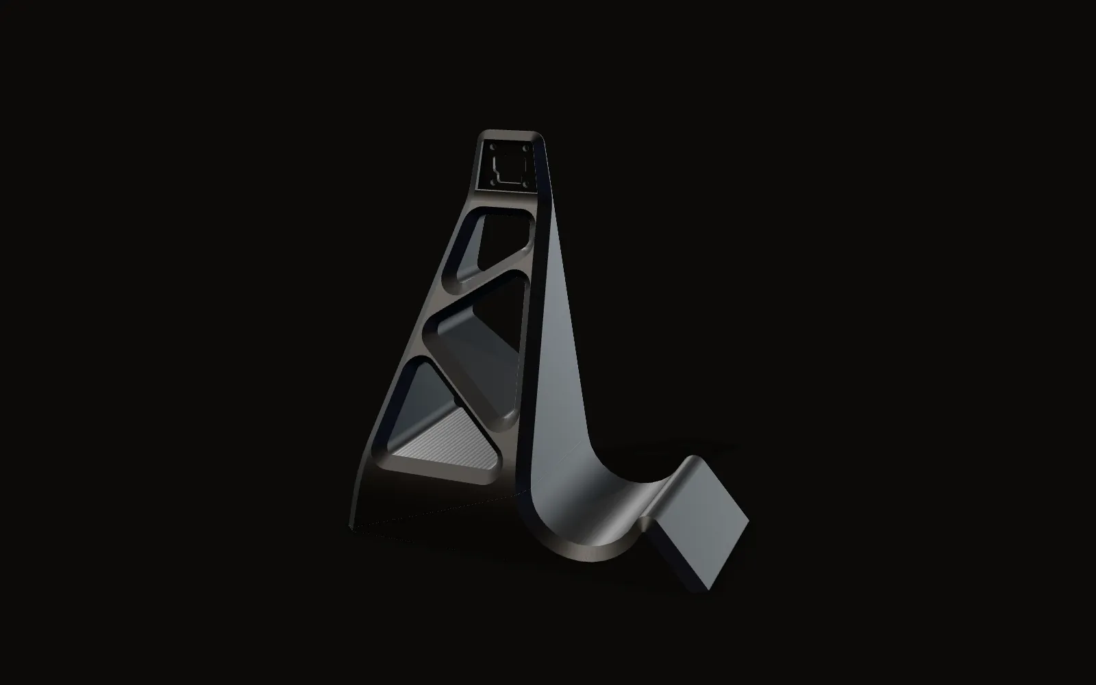
Both parts are in my CAD and both are printed in black. This is the real CAD of each; scroll to go around them.
Two printed parts
A tower that stands on the trainer and holds the sensor board at the flywheel's axle, and a two-piece clamp that holds the LCD on the handlebar.
The tower
It has to hold a board about 16 mm across well above the trainer's frame. Seen from the side it is a triangle, wide at the base and narrow at the top, with three pockets cut through the side and a solid curved wall along the back. The wires run up that wall to the board.
On the axle's line
The board screws to the plate at the top with four screws on a 16.7 mm square, and the middle of that square is 161 mm above the bottom of the base (both from the CAD). That line, dashed here, is where the flywheel's axle has to be.
A two-piece clamp
The display mount closes around the handlebar in two pieces. Four screws pass through both flanges, so the cap can only move straight along them: here it lifts off along those four axes.
Closed around the bar
In the CAD the two halves are drawn 10 mm apart. Brought together along the screws, their half circles meet in one 28 mm bore (from the CAD). Under the clamp is a solid block and a flat plate with screw holes for the LCD board.
My CAD of both parts, shown side by side. The dashed lines are the sensor axis and the clamp screw axes; there is no bike, trainer or LCD in the model. Dimensions come from the CAD.


Electronics
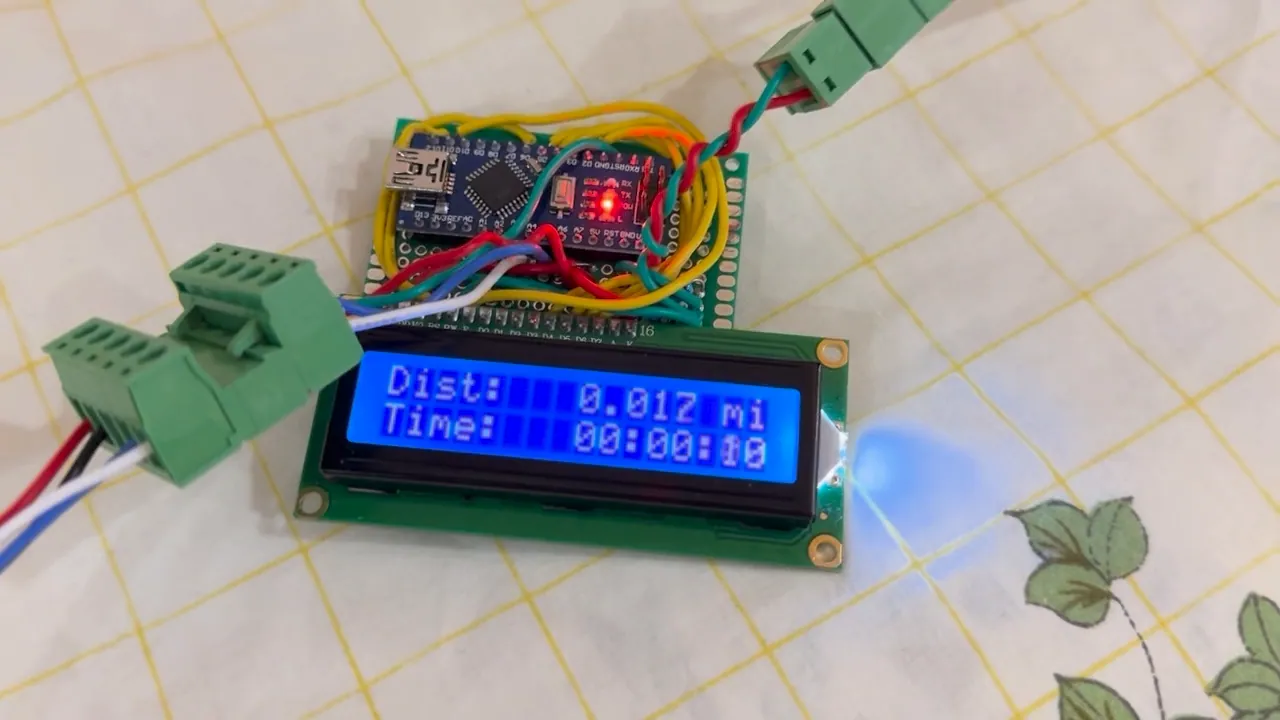
The controller is an Arduino Nano on a small perfboard, and the perfboard is soldered straight onto the back of the LCD's header. The Nano, the LCD and the wiring are one stack that mounts as a unit, and the sensor cable plugs into a green pluggable terminal on the board.
The sensor talks to the Nano over I2C. The LCD runs in 4-bit mode on six pins (RS on 12, E on 11, D4 to D7 on 5, 4, 3 and 2), and the code sets the LCD's contrast itself, with PWM on pin 6 at 75 out of 255.


The code
The code is on GitHub: github.com/jerryli08/bikeOdometer. I built it up one sketch at a time: the LCD alone (lcdTest), the sensor alone, printing its angle and the distance to the serial monitor (bikeMT6701Test), both together (bikeIntegrationTest), and then finalCode.
The sensor only knows an angle between 0 and 360 degrees, so every pass of the loop reads the new angle and subtracts the last one. If that change is more than half a turn, the code assumes the reading wrapped past 0 and corrects it by a full turn, so the change always lands between -180 and +180 degrees. The change as a fraction of a turn, times 6.68 in per roller turn, is the distance ridden since the last pass. The running total is kept in inches and shown in miles to three decimals, next to the time since the odometer was switched on.
Two more details: the final code subtracts the change (its comment says "assuming reverse direction"), so a falling angle counts as riding forward, and it clamps the total at zero, so the display never shows a negative distance.
Going backwards
Problem The distance went backwards
My commit that fixed it calls it the "going backwards bug". Before the fix, the integration sketch wrote both lines of the LCD and printed to the serial monitor on every pass of the loop, so every pass took a long time.
Fix LCD once a second
The final code writes the LCD once a second instead of on every pass. Updating the LCD takes much longer than reading the encoder, so writing it once a second shortens every loop enough for the encoder to be read properly. With a short loop the readings stay less than half a turn apart, which is what the wrap correction above needs.
Calculation How short does the loop have to be?
| One roller turn | 6.68 in of riding | my code |
|---|---|---|
| Largest change the wrap correction counts the right way | half a turn (180 degrees) per reading | my code |
| 1 mph | 17.6 in/s | 63,360 in / 3,600 s |
- At 1 mph the roller turns 17.6 / 6.68 = 2.63 turns a second = 949 degrees a second
- Readings stay under half a turn apart while speed × 949 × loop time < 180, so the top speed it counts right is 180 / (949 × loop time) mph
- 10 ms loop: 180 / 9.49 = 19 mph. 20 ms: 9.5 mph. 50 ms: 3.8 mph
Every millisecond the loop spends on the LCD lowers the fastest riding it can count: with a 20 ms loop, anything over about 9.5 mph is miscounted, as in the drawing above.
The math, not a measurement: I never timed the loop on the bike.
For testing, the display sat on the table while the wheel spun on the trainer; once the clamp was printed, it went on the handlebar and I rode.
On the bike
Clamped to the handlebar, the display shows the distance and the time since it was switched on, while the tower sits on the trainer at the flywheel's axle.
