← All projectsMIT Beaver Works Summer Institute (BWSI)Jul to Aug 2025
Autonomous Racing Drone
Capstone race winner
Led a team of five writing vision-guided autonomy for a race drone. We won the capstone race in 52 s, under half the second-best team’s time.
This was the capstone of the Autonomous Air Vehicle Racing course at the MIT Beaver Works Summer Institute (BWSI), which has a 5.8% acceptance rate.
I led a team of five writing the software for an autonomous drone race: a Holybro X500 quadcopter has to follow an LED line on the floor, past hoops, with nobody flying it. A downward camera finds the line in every frame with color segmentation and a least-squares line fit on a Raspberry Pi 5, and that becomes velocity commands for the flight controller. A forward camera is for obstacle avoidance: the hoops carry AprilTags.
We won the race in 52 seconds, and we were the only team to take off autonomously and complete the whole course in one run. Below: our line follower flying a lap as you scroll, the drone from our CAD, and how the code turns a picture of the floor into a velocity command.
Follow the line
Scroll to fly one lap. The drone runs the vision steps, constants and control law of our line-following script: every control tick it looks at the floor, finds the line again and sends a new velocity command. The inset is what the downward camera sees and what the code does to that picture; the readout is what the code sends.
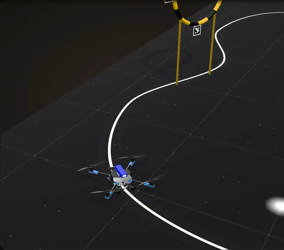
Take off over the line
The drone starts on the LED line. The script arms it and starts Offboard mode with a slow climb; here it levels off at 1.0 m, the script’s take-off height. The orange box on the floor is the patch the downward camera sees, and it grows as the drone climbs.
What the downward camera sees
Each time round the loop the script takes one 640 x 360 frame from the downward camera: the inset. The nose is at the bottom of the picture. Up close, the LED rope is a row of separate bright dots.
Dots into one bar
Dilate 30 x 30, erode 20 x 20, then keep only pixels from 250 to 255 in all three channels. The dots merge into one solid bar: the mask in the inset.
A line, and a point to chase
cv2.fitLineputs a straight line through the bar (green), and the script takes the point 100 px ahead along it (orange). That point’s offset from the image centre and the line’s angle become the forward, sideways and yaw-rate commands in the readout. One command, then the loop sleeps 0.5 s while the flight controller flies it.A hoop ahead
The forward camera, its view in blue, is for obstacle avoidance: the hoops carry AprilTags, lit here while they are in its view. Each hoop stands square across the path, and the drone flies straight through the middle of it.
Round the bends
Chasing a point ahead of the drone, not the nearest point, is what turns it into each bend before it gets there: the yaw rate follows the curves. The same law that centres it on the line also pushes it along, because on a straight the target is always ahead. On the way back it flies through the second hoop the same way.
A reflection on the floor
A round reflection comes into view, bright enough to pass the threshold, so the mask has two blobs. The script keeps the one with the longest side, the rope, and ignores the other. Then the drone is back over the start: one lap, with the line found in every frame.
A simulation on our CAD, not a recording: a JavaScript port of our script flies the lap ahead of time, and the scroll picks the moment. From our script: the image processing, the gains and limits, the 0.5 s between commands and landing after 10 frames with no line. Assumed for the page: the drone holds 1.0 m (the script’s take-off height), the flight controller follows each command with a 0.3 s lag, and the camera has the 66° lens of a standard Camera Module 3. The course, the LED rope, the hoops, the reflection and the climb are drawn for the page. Each hoop stands square across the drone’s path, centred on it, and the drone flies through without reacting to it: our repo has no forward-camera code. Some steps cover more of the flight than others; that changes time only, and the readout is what the code sent at that moment.
The race
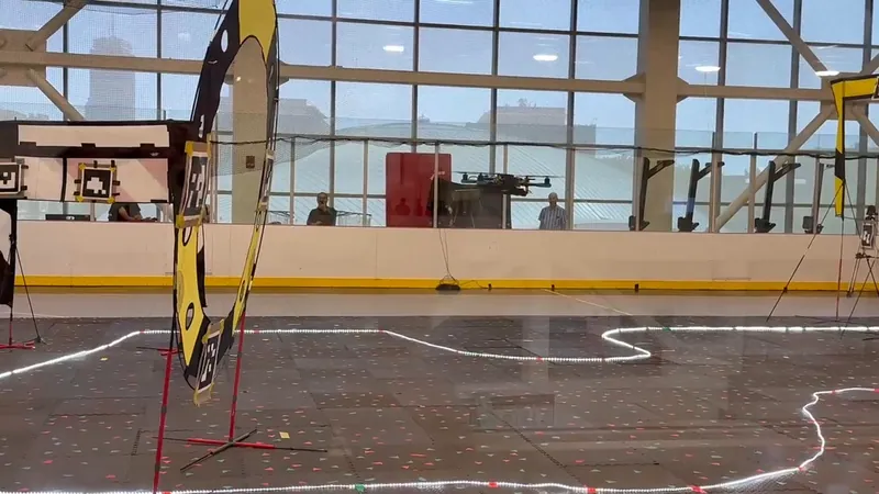
The course was an LED rope laid on the dark floor of a large hall, in a loop with S-bends, and the drone had to follow it on its own. Along the course stood obstacles: hoops with AprilTags on them. Five teams raced.
The drone
Our CAD, turned by the scroll, with the parts that make it autonomous lit up one group at a time.
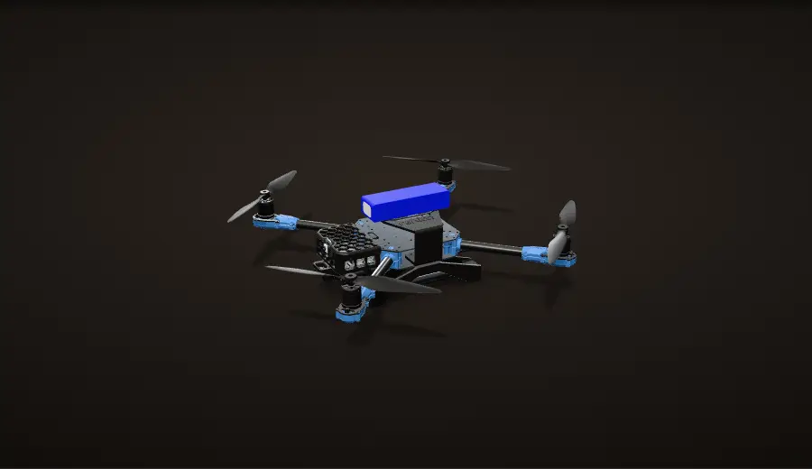
A Holybro X500 V2
A carbon quadcopter with four 2216 880 KV motors, 500 mm apart on the diagonal, turning 10 x 4.5 in props on a 4S LiPo. What makes it autonomous sits on the nose.
The Pi 5 and the forward camera
A Raspberry Pi 5 on the front payload plate, with the forward camera (a Raspberry Pi Camera Module 3) in the same printed mount, under a printed cover.
Under the nose
A second printed mount holds the downward camera, another Camera Module 3, next to an ARK Flow board: an optical flow camera and a distance sensor that look at the floor.
Both cameras, 14 cm ahead
In the CAD both camera sensors sit on the centreline about 14 cm ahead of the centre of the frame. The forward one looks straight ahead at top-plate height; the downward one looks at the floor from 16 mm under the bottom plate.
Power
The 4S LiPo rides on top of the frame in printed mounts, over the power module.
The printed parts
Everything lit here is 3D printed: the mount and cover on the nose, the mount under it, the battery mounts and the landing gear mounts, which carry the frame low.
Our CAD with the screws left out.


The software stack
The line follower runs on the Raspberry Pi as one Python program:
| Layer | What we used |
|---|---|
| Cameras | Two Raspberry Pi Camera Module 3s; the downward one is read with the Picamera2 library at 640 x 360 |
| Vision | OpenCV and NumPy |
| Control loop | Python 3 with asyncio |
| Talking to the drone | MAVSDK-Python, which talks over gRPC to mavsdk_server (the linux-arm64 build) running on the Pi |
| Link to the flight controller | MAVLink over the Pi’s UART (/dev/ttyAMA0, 57,600 baud in the line follower) |
| Flight controller | Offboard mode, taking body-frame velocity and yaw-rate setpoints |
| Camera calibration | OpenCV chessboard calibration (below) |
| Prototyping | Jupyter notebooks |
One frame in
The downward camera looks at the floor under the nose.
camera.capture_array()in Picamera2 hands the script a 640 x 360 image each time round the loop.Find the line
OpenCV and NumPy dilate, erode and threshold the frame, keep the longest blob and fit a line to it. The next section goes through each step.
PD control
Pixel and angle errors in; forward, right and yaw-rate commands out, rotated from the camera frame to the drone and clamped.
Over MAVLink
Our asyncio program sends one body-frame velocity and yaw-rate setpoint, then sleeps 0.5 s. MAVSDK-Python talks over gRPC to
mavsdk_server(the linux-arm64 build) running on the Pi, which speaks MAVLink to the flight controller over the Pi’s UART.The flight controller flies it
The Pi does not fly the drone. The flight controller keeps it stable and holds whatever velocity it is told; our code decides that velocity: go forward this fast, slide right this fast, turn this fast. The flight controller stays in charge of the motors the whole time.
From the side
The forward camera is for obstacle avoidance: the hoops on the course carry AprilTags. The ARK Flow board under the nose is an optical flow camera and a distance sensor looking at the floor. During test flights, teammates stood by with RC transmitters, ready to take over by hand.
The path of one command, from a camera frame to the motors.
Seeing the line, one step at a time
One downward-camera frame through every step of our script, computed live on this page with the same code as the flight at the top. The frame is drawn for the page: a bend in the rope and a wide round reflection.
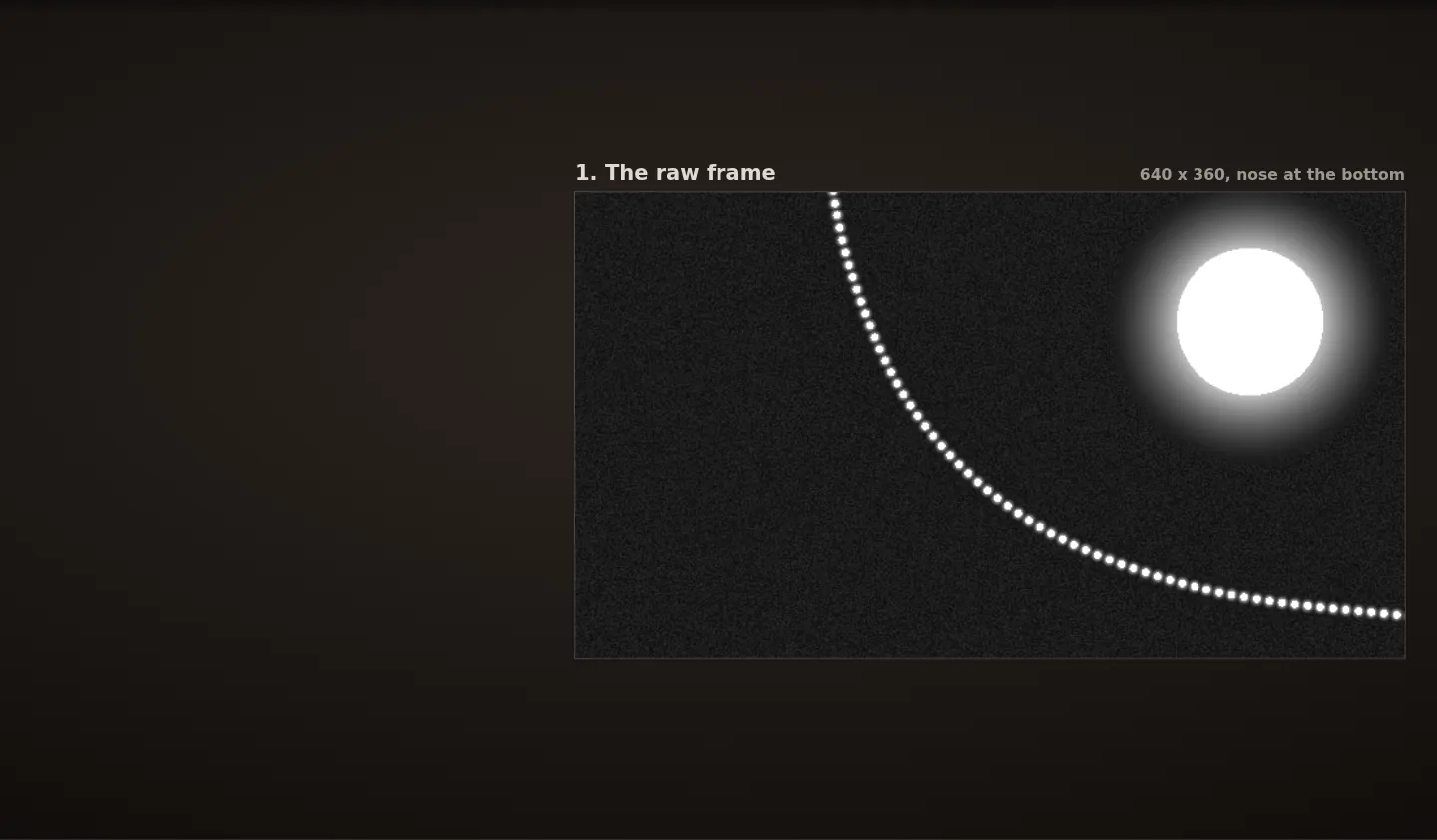
The raw frame
One 640 x 360 frame, nose at the bottom. The rope reaches the camera as separate dots, not a line.
Dilate, 30 x 30
cv2.dilategives every pixel the brightest value in the 30 x 30 square around it. Each bulb grows by 15 px each way, and neighbouring bulbs merge into one bar. The reflection grows too.Erode, 20 x 20
cv2.erodedoes the opposite with a 20 x 20 square and takes most of that growth back. The gaps between bulbs stay closed, and the rope is left as one solid bar about 10 px wider than a bulb.Threshold, 250 to 255
cv2.inRangekeeps only pixels that are almost fully saturated in all three channels. The dim glow around the bulbs drops out; the rope and the reflection stay.Keep the longest blob
cv2.findContoursoutlines each blob, and the script sorts them by the long side ofcv2.minAreaRect, the smallest rotated rectangle around each one. It keeps the longest blob, not the biggest: here the reflection has more area than the rope, but its long side is 122 px against the rope’s 557.Fit a line
cv2.fitLinewithDIST_L2fits a straight line to the kept blob’s outline by least squares on perpendicular distance. It returns a direction and a point on the line, so a line running straight down the picture is no harder than any other.Look 100 px ahead
The script turns the direction to point down the picture, toward the nose, and takes the point 100 px ahead along it. The position error is the offset from the image centre to that point. The angle error is the angle between the line and straight down the picture,
atan2(-vx, vy).Velocity and yaw commands
Proportional-derivative control turns the errors into commands: 0.001 m/s per pixel of error and 0.2 °/s of yaw rate per degree. A fixed rotation takes them from the camera’s axes to the drone’s: forward is image y and right is minus image x. The previous errors here are the same as the current ones, so the derivative terms are zero and the numbers are the proportional terms.
What each step is there for
Problem The rope is not a line to a camera
Up close an LED rope is a row of separate bright dots with dark gaps between them. Thresholded as it is, the rope falls apart into dozens of small blobs, each one or two bulbs long.
Fix
Dilate with a 30 x 30 kernel first, so neighbouring bulbs grow into each other, then erode with a 20 x 20 kernel to take most of the growth back. What is left is one solid bar along the rope.
Problem Other bright things
The rope is not the only bright thing a downward camera can see. A light reflected in the floor is bright too, and it can be bigger than the part of the rope in view.
Fix
Two filters. The threshold keeps only pixels that are almost fully saturated in all three channels, and of the blobs that survive, the script keeps the one with the longest minimum-area rectangle, not the one with the most area. A reflection is round; the rope is long and thin. The flight at the top passes one near the end of its lap.

Problem y = mx + b cannot follow a line straight ahead
In my computer vision coursework I fit the line as y = mx + b by least squares on the bright pixels:
m = (mean(x) * mean(y) - mean(x*y)) / (mean(x)^2 - mean(x^2))
b = mean(y) - m * mean(x)
That form measures error vertically and needs a finite slope. On our drone the camera is mounted so that forward runs straight down the image, so when the drone is on the line, the line is vertical in the picture: the points barely vary in x, the denominator (minus the variance of x) goes to zero and the slope blows up.
Fix
The flight script fits the line with cv2.fitLine and DIST_L2 instead. It minimises the perpendicular distance from the points to the line and returns a unit direction and a point, not a slope, so it works the same at every angle, including straight ahead.

From a line to velocity commands
The fitted line becomes three numbers each control tick:
1. Pick a point to chase. Turn the line’s direction so it points toward the nose, then take the point 100 px ahead along the line from the fitted point. Chasing a point ahead of the drone, not the nearest point, is what makes it turn into a bend.
Calculation How far ahead is 100 px?
| Camera height over the floor | 1.0 m | the script’s take-off height, assumed held (as in the flight above) |
|---|---|---|
| Camera Module 3 field of view | 66° x 41° | Raspberry Pi product brief |
| Frame | 640 x 360 px | our script |
- Floor in view: 2 × 1.0 m × tan(66° / 2) = 1.30 m across, and 2 × 1.0 m × tan(41° / 2) = 0.75 m from the nose side to the tail side
- Scale: 1.30 m / 640 px = 2.0 mm per pixel (0.75 m / 360 px = 2.1 mm the other way)
- Look-ahead: 100 px × 2.0 mm = 0.20 m along the line; the nose edge of the picture is 180 px = 0.37 m from the centre
- Dilate 30 x 30: each bulb grows 15 px, 3 cm, each way, so any gap up to 30 px, about 6 cm of rope, closes
The drone chases a point about 20 cm ahead, a little over half way to the edge of the floor it can see, and the dilation bridges any gap between bulbs shorter than about 6 cm.
Estimate: assumes the full field of view at 640 x 360 and the camera 1.0 m over a flat floor; at other heights every length scales with the height.
2. Measure the error. The pixel offset from the image centre to that point is the position error; the script treats the image centre as the drone’s centre. The angle between the line and the image’s forward axis is the heading error, zero when the line runs straight ahead.
3. PD control on both, in the camera’s frame, with the derivatives taken over a fixed 0.1 s:
cx = 0.001 * ex + 0.00015 * (ex - ex_prev) / 0.1     # m/s per pixel
cy = 0.001 * ey + 0.00015 * (ey - ey_prev) / 0.1
wz = 0.2 * angle + 0.2 * (angle - angle_prev) / 0.1   # deg/s per deg
4. Rotate into the drone’s frame and clamp. The downward camera is turned on the drone: the bottom of the image is the nose and the right of the image is the drone’s left. One fixed rotation maps the commands: forward = cy, right = -cx, yaw rate = wz. Speeds are limited to 0.5 m/s and the turn rate to 90 °/s.
R_dc2bd = [[ 0, 1, 0],
           [-1, 0, 0],
           [ 0, 0, 1]]     # forward = image y, right = -image x, yaw unchanged
5. Send and wait. The result goes to the flight controller as one body-frame velocity and yaw-rate setpoint with zero vertical speed, so the drone holds its height. Then the loop sleeps 0.5 s, and the flight controller keeps flying that setpoint until the next one arrives.
Because the look-ahead point sits 100 px ahead of the image centre, the same law that centres the drone on the line also pushes it along the line: on a straight the target is always ahead, so the drone keeps moving toward it.
If a frame has no line in it, the script sends nothing new and captures again at once, counting the miss; it is written to land after 10 such frames. The Frames with no line row in the flight’s readout counts them.
Obstacles: the forward camera and the AprilTags

The forward camera is for obstacle avoidance. The obstacles on the course are hoops with AprilTags on them: square markers whose four corners, seen by a calibrated camera, give the tag’s position and orientation.
Calibration comes first, because a tag’s pixels only turn into metres once the camera’s focal length, optical centre and lens distortion are known. Our calibration script uses a printed chessboard with 7 x 7 inner corners and 25 mm squares, photographed 70 times at different angles. It finds the corners, refines each one to sub-pixel accuracy with cv2.cornerSubPix, and solves for the camera matrix and distortion coefficients with cv2.calibrateCamera.
In the flight at the top of the page the hoops stand square across the path and the drone flies through them without reacting to them: our repo has no forward-camera code to port.
The code, program by program
The line follower is one asyncio program. It connects to the flight controller through mavsdk_server on the Pi’s UART, arms, starts Offboard mode with a slow-climb velocity setpoint, then loops: capture, detect the line, compute the velocity, send it, sleep 0.5 s. detect_line() holds the vision steps above, get_velocity() the look-ahead point and errors, and pid() the gains and the previous errors.
Two smaller programs in the repo exercise the same path without the camera. An open-loop MAVSDK test takes off, switches to Offboard, flies forward at 1 m/s for 4 s, spins at 90 °/s for 4 s and lands, which checks the command path end to end. A ROS 2 node (rclpy) does the same Offboard handshake through MAVROS: it streams position setpoints, requests OFFBOARD mode and arming through the MAVROS services, and slides the setpoint forward.
An earlier draft of the line follower is in the repo too, with the same structure and pid() and get_velocity() still empty. Between the draft and the line follower:
| Earlier draft | Line follower | |
|---|---|---|
| Speed limits | 1.0 m/s in x, y and z | 0.5 m/s |
| Loop | one command per second | one every 0.5 s |
| No line in a frame | land at once | keep going; land after 10 frames with no line |
| Serial link | 921,600 baud | 57,600 baud |
| Image | 640 x 380 | 640 x 360 |
Calculation How far can it fly on one command?
| Earlier draft: speed limit, time between commands | 1.0 m/s, 1 s | our earlier draft |
|---|---|---|
| Line follower: speed limit, time between commands | 0.5 m/s, 0.5 s | our line-following script |
| Floor seen ahead of the image centre | 0.37 m | the look-ahead calculation above |
- Draft: 1.0 m/s × 1 s = up to 1.0 m between two looks at the floor
- Line follower: 0.5 m/s × 0.5 s = up to 0.25 m
- Against the floor in view: 1.0 / 0.37 = 2.7 times it; 0.25 / 0.37 = two thirds of it
At the draft’s limits one command could carry the drone almost three times past the floor the camera sees ahead of it before the next look; at the line follower’s limits it covers at most two thirds of it.
Upper bounds at the speed limit, ignoring the flight controller’s lag; the camera height is assumed as above.

From flying by hand to the race
Jul 7 to 11
Build it, fly it by hand
We assembled the X500 and flew it by hand in the flight cage before any autonomy.
Flying by hand in the flight cage, early July Mid July
The vision and control groundwork
Coursework in image formation, OpenCV, linear regression on downward-camera frames, coordinate frames and feedback control, all in Jupyter notebooks. The line follower uses the same pieces: thresholding, morphology, a line fit and feedback control.
Late July
The rebuild
The printed housing went on the nose for the Pi and the forward camera, the downward camera and the ARK Flow board went underneath, and the battery moved on top.
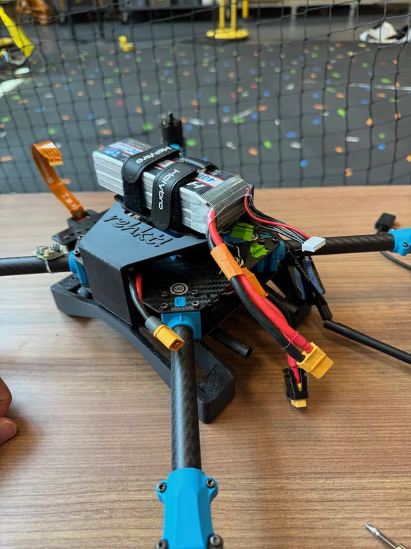
Jul 26: the printed housing on the nose and the battery strapped on top 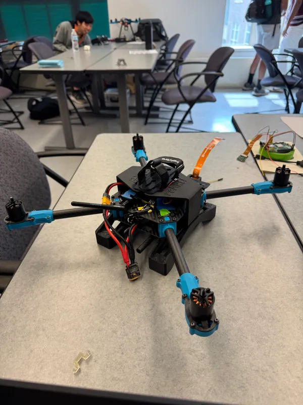
The same build from above, low on the printed landing gear mounts End of July
A rectangle of LED rope in the cage
An LED rope taped to the cage floor in a rectangle: lift off from the line, follow the straight, take a 90° corner, run the next side past the team tables, and reach the hoop in the far corner.
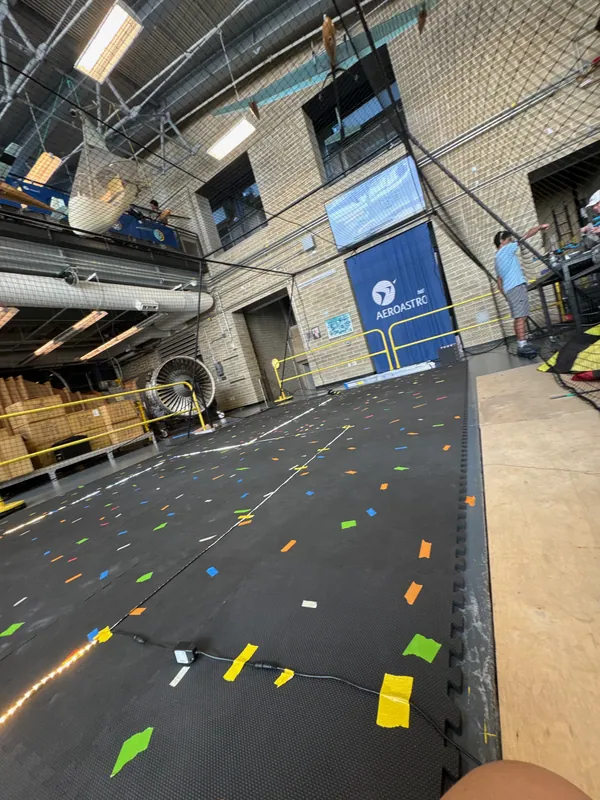
Jul 29: the practice course, LED rope taped to the cage floor 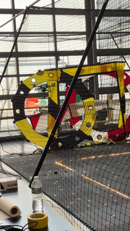
The ring hoops at the far end of the practice cage Lifting off from the line Start of August
A harder layout
The rope was laid again with diagonal legs and a zig-zag, and a gate went up over the line.
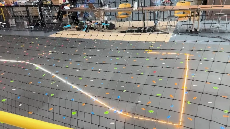
The new layout: diagonals and a zig-zag A gate over the line in the cage Race day
52 seconds, first of five
On the race course in the hall: our run took 52 seconds, and we were the only team to take off autonomously and finish the whole course in one run.
The race course: an LED loop with S-bends and the hoop frames


