← All projectsPersonal projectMay to Jun 2025
5-Bar Pen Plotter
Parallel robot with inverse kinematics
A 5-bar parallel robot that draws from Cartesian coordinates, built to learn the linear algebra behind robot arms.
I built a 5-bar pen plotter to learn how the linear algebra behind robot arms turns into motion. Two NEMA 17 steppers on TMC2209 drivers turn two 3D printed arms, two more links join them at the pen, and an Arduino Nano turns every x-y point into two motor angles with inverse kinematics, solved again on every pass through the loop so the pen follows straight lines.
I designed it in Fusion 360, printed it, wired it on perfboard and wrote the code in C++, from single-motor tests up to a program that writes my name. The code is on my GitHub.
The real linkage, writing my name
My CAD, turning about its real pivots. Scrolling is the program clock: at every moment the pen target is what my final sketch computes, my inverse kinematics turns it into two motor angles, and the ink follows the pen. The readout shows the numbers the Arduino works with.
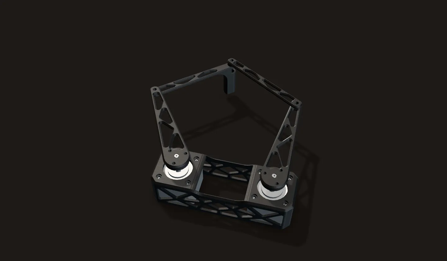
Home
Two NEMA 17s 100 mm apart turn 100 mm arms, and two 100 mm forearms meet at the pen. The code has no homing: it calls this pose home (both arms at 90°, pen at (50, 186.6) mm), so the arms must start here.
Faint dashes: the path to come. Blue dashes: the fold line, where the two forearms fall into one straight line.
J and e
From home the pen travels to the start of the J. The pen never lifts, so that travel is drawn too. Every stroke of the name takes 200 ms: on each pass through the loop the program works out how far through the stroke it is, puts the target that far along the straight line, solves the inverse kinematics and sends both motors there.
r and r
With no pen lift the whole name is one continuous line. Every letter starts and ends on the baseline at y = 130 mm, and strokes like the arm of each r go out and back over themselves.
y
The tail of the y goes down to y = 100 mm, the closest the name comes to the fold line. Watch the pen travel per microstep in the readout: about 0.2 mm in the letters, up to 0.7 mm at the bottom of the y.
L, i and home
40 path entries and 9.9 s of program time: a name 140 mm wide with 20 mm letters. The last move takes the pen home in 1.5 s.
The test square
Next, the 75 mm square from my first x-y program, run here through the final loop: straight lines in x and y, inverse kinematics on every pass. Its bottom edge, at y = 75 mm, lies just past the fold line.
Through the fold line
Coming down the right edge, the pen crosses the fold line at y = 76.3 mm. There the two forearms lie in one straight line (lit blue) and the motors no longer pin the pen down: the closer it gets, the further one microstep moves the pen.
Past the line, the pen joint sits on the motors' side of the elbows. The linkage has folded through.
Along the bottom and home
The whole bottom edge runs 1.3 to 11.6 mm past the fold line, and the left edge folds back through it at y = 76.3 mm on the way up. The math stays smooth the whole way. How far one step moves the pen does not.
Computed from my CAD's link lengths and my code. How my first program drew this square is further down.
The linkage is my Fusion CAD with its real 100 mm links and pivot axes; the motion is my code's inverse kinematics, motor limits and path timing, with the scroll as the clock. The grid is 10 mm. The pen, paper and board are not in the CAD, so the ink is drawn on the table under the pen.
What a 5-bar is
A 5-bar linkage has five links counting the base: the two motor arms, the two forearms, and the fixed distance between the motors. The motors sit side by side and each turns one arm. Each forearm hangs off the end of an arm, and the two forearms meet at the pen.
With both motors held still the loop is rigid, so two motor angles give exactly one pen position for a given way the loop is folded. That makes it a parallel robot: both motors share the job of placing one point, and neither motor rides on the other, so the only moving parts are four thin plates.

In the CAD the two motor shafts are 100 mm apart and all four links are 100 mm hole to hole. My code uses the same two constants, BASE_SEPARATION = 100 and ARM_LENGTH = 100. Equal links make each side of the robot an isosceles triangle, which keeps the inverse kinematics down to a few lines of trigonometry.
The CAD
My Fusion 360 model, in the pose it was saved in. Screws are left out.
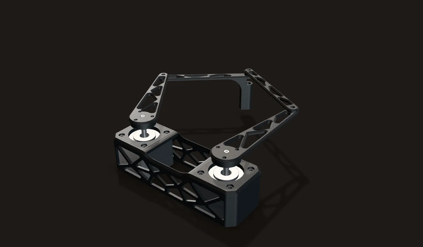
Two motors, four links
Both NEMA 17s sit in one printed housing. Each turns a 3 mm printed arm, and the two forearms meet at the pen joint. Every link is 100 mm between its pivots.
Three levels
Pulled apart along the joint axes, in their real order. The 3 mm plates sit on three levels: both motor arms in the middle, the pen forearm under its arm, and the right forearm on top of its arm. A 3 mm spacer fills the gap between the two forearms at the pen joint.
The pen is on the joint axis
Cut through the pen joint. The pen tube hangs under the pen forearm, and its 6.4 mm bore is concentric with the joint. So the pen tip is exactly the point the inverse kinematics solves for, with no offset to correct.
Direct drive
Each motor arm bolts to a flange hub on the 5 mm motor shaft, with three screws. There are no belts or gears, so the arm turns exactly as far as the motor: 0.1125° per microstep, about 0.2 mm at the elbow (computed).
One part sets the spacing
Both motors sit in one printed housing with lattice sides, so the 100 mm between the motor shafts, the number all of the math depends on, is set by a single part.
Building it
I 3D printed the housing, the arms and the forearms. The housing holds both motors shafts up, and the flange hubs sit on the shafts under the arms.


The first design in Fusion had arms with long slot cutouts. The final arms are 3 mm plates with triangular cutouts.


Inverse kinematics: two triangles
Cartesian in, two angles out
Put the left motor at (0, 0) and the right motor at (100, 0), in mm, with y pointing away from the motors. The program is given a pen point (x, y) and has to find the two motor angles that put the pen there.
The left triangle
The left arm, the pen forearm and the line from the left motor to the pen make a triangle with two 100 mm sides. Call that line D1. It points at atan2(y, x), and because the triangle is isosceles the arm sits acos(D1 / 200) to one side of it.
The right triangle
The same on the right, measured from (100, 0): the angle of D2, minus its own half-angle. Two lines of trigonometry per arm, and nothing else.
Two answers per arm
Each triangle folds either way, so every reachable point has two whole-robot solutions: both elbows out, or both in. My code builds both, throws out any that break a motor limit (left arm 15° to 270°, right arm −90° to 165°) and keeps the one with the larger left minus right angle: the arms spread widest.
Out of reach
If either D is more than 200 mm, the two 100 mm links cannot reach. The code then holds both motors where they are, so the pen stops at the edge of the workspace while the target keeps going.
Top view, drawn to scale. The numbers are computed live by a copy of my computeAll5BarSolutions and selectBestSolution.
The code, built up one sketch at a time
The repo is five Arduino sketches in C++, each one step further than the last. All of them drive the two TMC2209s through the AccelStepper library in step and direction mode, at 3,200 microsteps per revolution, a 4,000 steps/s speed limit and 8,000 steps/s² acceleration: 450°/s and 900°/s² at the arm (computed).
stepperSetupTest: enable both drivers and move one motor at a time, 320 microsteps on the left and 640 on the right, and back.simultaneousTest: the same moves, but calling each motor'srun()insideloop()instead of blocking, so both motors move at once.stepperTimedTest: moves written as joint angles with a duration. Each loop works out how far through the move it is and sets both targets that far along, so both arms arrive together.cartesianTest: the first x-y program. It solves the inverse kinematics for each corner of a 75 mm square, printing both solutions to the serial monitor, then moves between the corners with the timed joint moves from the step before.cartesianPathing, the final one: every pass throughloop()finds the point on the current line segment for the elapsed time, solves the inverse kinematics for that point, and sends both motors there. This is the program that writes "Jerry Li".
A path is an array of x, y and a duration in ms for each move. The final loop, in order:
progress = elapsed / duration                    (0 to 1 along this segment)
x = start.x + (end.x - start.x) * progress
y = start.y + (end.y - start.y) * progress
computeAll5BarSolutions(x, y)                    both solutions, degrees
idx = selectBestSolution(sols)                   legal, arms spread widest; none: hold
leftMotor.moveTo(degToSteps(left))               degrees to microsteps
rightMotor.moveTo(degToSteps(right))
leftMotor.run(); rightMotor.run()                AccelStepper steps toward the targets
elapsed >= duration: next segmentCalculation How far does the first program bow the top edge?
| Top edge of the test square, left end | (12.5, 150) mm | my cartesianTest |
|---|---|---|
| Top edge, right end | (87.5, 150) mm | my cartesianTest |
| Links and motor spacing | 100 mm | my CAD and my code |
- Inverse kinematics at the corners, arms spread widest: left 126.42° and right 90.52° at (12.5, 150); left 89.48° and right 53.58° at (87.5, 150)
- Halfway in motor angles: left 107.95°, right 72.05°
- Elbows there: (100 cos 107.95°, 100 sin 107.95°) = (-30.8, 95.1) and (100 + 100 cos 72.05°, 100 sin 72.05°) = (130.8, 95.1), 161.6 mm apart
- Pen: midway between the elbows and √(100² - 80.8²) = 58.9 mm beyond them: (50, 154.0)
Halfway along, moving the motor angles in a straight line puts the pen 4.0 mm off the edge it should be drawing. Solving the inverse kinematics on every pass keeps it on the line.
Calculation Can the motors keep up with 200 ms strokes?
| Time per stroke of the name | 200 ms | my cartesianPathing path |
|---|---|---|
| Longest stroke, the tail of the y | 50 mm | my path |
| Speed limit per motor | 4,000 microsteps/s | my code |
- Pen speed on the longest stroke: 50 mm / 0.2 s = 250 mm/s
- Motor speed that stroke asks for, from the inverse kinematics every 0.5 ms along it: at most 805 microsteps/s
- Fastest anywhere in the name: 2,317 microsteps/s, on the right motor at the start of the J's top stroke, (-30, 150). There the right arm and forearm span 198.5 of their 200 mm, almost straight, so a little pen travel takes a lot of turning
- 2,317 / 4,000 = 58 % of the limit
No stroke of the name asks either motor for more than 58 % of the speed limit.
Speed only: the 8,000 steps/s² acceleration limit is not modelled here. Computed from my path and code, not measured.
Straight on paper is not straight in motor angles
Two corners
The top edge of the 75 mm square from
cartesianTest, from (12.5, 150) to (87.5, 150). The inverse kinematics gives both motor angles at each corner.The first program
Problem Straight in motor angles is curved on paper
cartesianTestsolved the inverse kinematics only at the corners, then moved both motor angles in a straight line between them. For a 5-bar a straight line in motor angles is a curve on paper: with my link lengths the top edge bows about 4 mm.The final program
Fix
cartesianPathingmoves the target in a straight x-y line and solves the inverse kinematics again on every pass through the loop, so every short move of the motors heads for a point on the straight edge.Worse near the fold line
Both bottom corners sit just past the fold line. Moving the motor angles in a straight line between them asks for elbow positions up to 205.4 mm apart, further than two 100 mm forearms can reach: no pose of the real linkage matches those angles. The final program's straight x-y line takes the same edge without trouble, as in the drawing run at the top of the page.
Computed from my code and my CAD's link lengths: angles from the inverse kinematics at the corners, pen positions from the forward kinematics of the in-between angles.
Getting ink on paper
The plotter stands on a stack of books and the paper lies on notebooks in front of it. The pen sits in the tube on the pen joint, pointing straight down.
Problem The pen never touched the paper
On the first run the arms traced the square in the air, and the pen left no line.
Fix
One more notebook under the paper brought it up to the pen, and the next run drew.
Problem No way to lift the pen
There are only two motors, so the pen is down for the whole program, and anything drawn is one continuous line, including the moves to and from home.
Fix
The name's path works with that: every letter starts and ends on the baseline, and strokes like the arm of each r go out and back over themselves.

A library of shapes
The same linkage and the same loop, running a library of drawings. The chips at the top of the readout are the library: my name and the square are the exact paths from my code (drawn above); the other five are new, drawn the same way as one continuous line and placed in the stiff middle of the workspace.
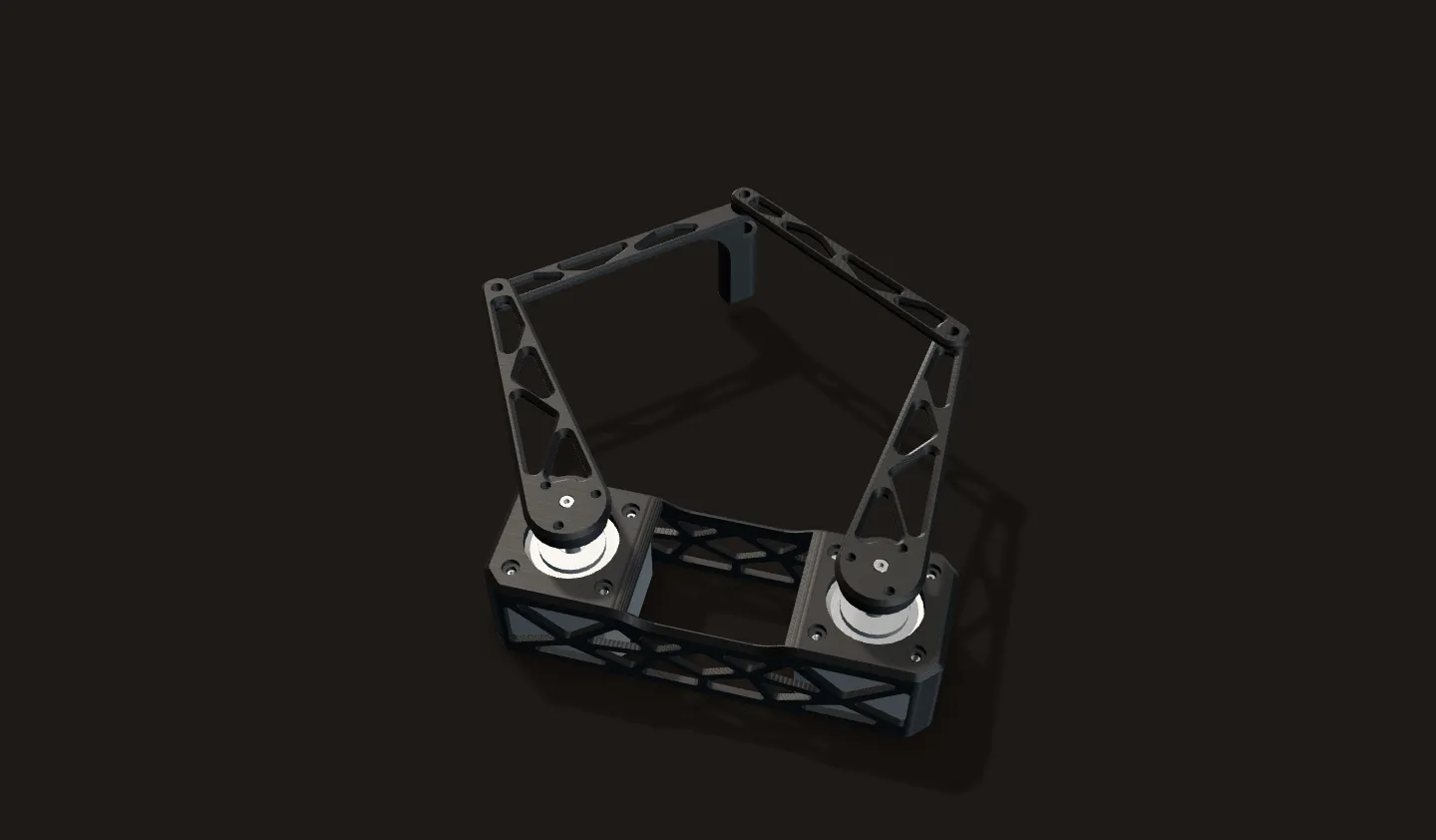
Circle
A 60 mm circle as 72 short straight moves of 40 ms. Between two entries the loop still interpolates in x and y, so the pen follows the polygon exactly; at this spacing it reads as a circle.
Heart
Two lobes from one parametric curve, starting and ending at the dip in the top so the travel from home joins it cleanly.
Triangle
An equilateral triangle with 60 mm sides: three straight x-y lines, each with the inverse kinematics solved on every pass.
House
One stroke: the roof, the walls, a door drawn up from the floor line, and the line under the roof last.
UIUC
Block letters 30 mm tall in the style of my name: joined along the baseline, with strokes that retrace themselves.
New drawings (circle, heart, triangle, house, UIUC) are paths in the same format as my code: x, y and a duration per move, from home and back. Every point of every path solves with the arms-spread-wide solution, inside the motor limits.
Where the linkage is weak
One microstep, everywhere
The map shows how far one microstep of one motor moves the pen at each point it can reach. Brighter means further. Most of my name sits in the dark, stiff middle, where one step moves the pen 0.14 to 0.27 mm.
In the letters
At the top corner of the square the pen moves about 0.2 mm per step, close to the 0.2 mm the elbow moves. Here both motors pin the pen down well.
Toward the fold line
Down the square's right edge the forearms turn toward one straight line, and a step moves the pen further and further: 3 mm at y = 80, and without limit at y = 76.3, where they line up. There the pen can slide across that line (the blue arrows) with both motors standing still.
Past it
Past the line the pen joint opens beyond 180°: the linkage has folded through. At the square's bottom corners one microstep moves the pen about 8 mm, and the whole bottom edge lies in this band. My name never comes closer than y = 100 mm.
Computed from my CAD's link lengths and the 0.1125° microstep, with the velocity equations of the loop. Nothing here was measured on the plotter.
Electronics
An Arduino Nano and two TMC2209 stepper drivers sit on a perfboard, with screw terminals for the motor leads. Each driver takes step, direction and enable from the Nano: pins 9, 8 and 10 for the left motor, and 3, 2 and 4 for the right. The drivers run 1/16 microstepping, which turns the motors' 200 full steps per revolution into 3,200. Both drivers are enabled (EN held low) from the start of the program to the end.
Calculation How far does one microstep move the arm?
| Microsteps per motor turn | 3,200 | my code (STEPS_PER_REV): 200 full steps at 1/16 |
|---|---|---|
| Motor to elbow | 100 mm | my CAD and my code |
| Speed limit | 4,000 steps/s | my code (AccelStepper) |
| Acceleration limit | 8,000 steps/s² | my code (AccelStepper) |
- Angle per microstep: 360° / 3,200 = 0.1125°
- Elbow travel per microstep: 100 mm × 0.1125° × π / 180 = 0.196 mm
- Top speed at the arm: 4,000 × 0.1125° = 450°/s = 7.85 rad/s, so the elbow can move up to 100 mm × 7.85 = 785 mm/s
- Acceleration at the arm: 8,000 × 0.1125° = 900°/s²
With direct drive at 1/16 microstepping one step moves the elbow about 0.2 mm, and in the stiff middle of the workspace, where the name is written, the pen moves 0.14 to 0.27 mm per step (the map above).
Computed from my code and my CAD's link lengths, not measured.


How it came together
May 21, 2025
CAD and the first print
The first design in Fusion 360, with slotted arms. The motor housing went on the printer the same evening.
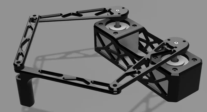
My first render, May 21 May 23
First assembly
Both motors in the housing and the whole linkage together for the first time. The perfboard with the Nano and both drivers followed on May 27 and 28.
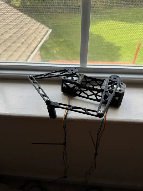
First full assembly, May 23 Tests
Moving the motors
The test sketches go from one motor at a time, to both together, to timed joint moves, before any x-y math.
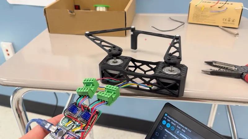
An early motor test: the left arm swung out Drawing
Ink on paper
The first run missed the paper, and one more notebook fixed it. Then the square and, with the final sketch, my name. The code is in the repo's one commit, on June 13, 2025.
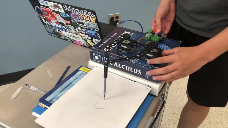
The setup: the plotter on a stack of books, the paper in front of it


Results
The plotter draws whatever it is given as x-y points. The final program writes "Jerry Li", 140 mm wide with 20 mm letters, from 40 waypoints in 9.9 s of program time.
